Fuel-cell compressed-air supplying device

Inactive Publication Date: 2007-03-29
JTEKT CORP
View PDF14 Cites 22 Cited by
  • Summary
  • Abstract
  • Description
  • Claims
  • Application Information

AI Technical Summary

Benefits of technology

[0015] With the fuel-cell compressed-air supplying device according to the present invention, the rotation shaft is supported in both the radial and axial directions by the foil bearings (dynamic-pressure gas bearings), which can suppress the reduction of the fatigue life of the bearings due to high-speed rotation and also can eliminate the necessity of providing the function of circulating lubricating oil, thereby enabling the reduction of the size of the compressed-air supplying device.
[0016] Further, in the case where the fuel-cell compres

Problems solved by technology

In fuel-cell apparatuses for use in fuel-cell vehicles, it has become a critical challenge to reduce the sizes, costs and weights of the fuel-cell apparatuses, and there has also been a need for further reducing the sizes of the compressed-air

Method used


Image

  • Fuel-cell compressed-air supplying device
  • Fuel-cell compressed-air supplying device
  • Fuel-cell compressed-air supplying device

Examples


Embodiment Construction

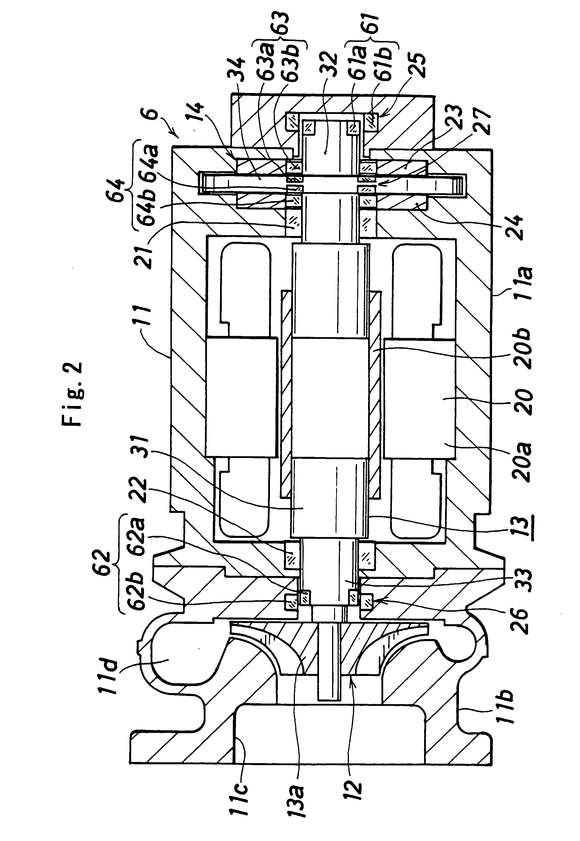
[0024] There will be described an embodiment of the present invention, with reference to the drawings. In the following description, the right and the left in FIG. 2 will be designated as front and back, respectively.

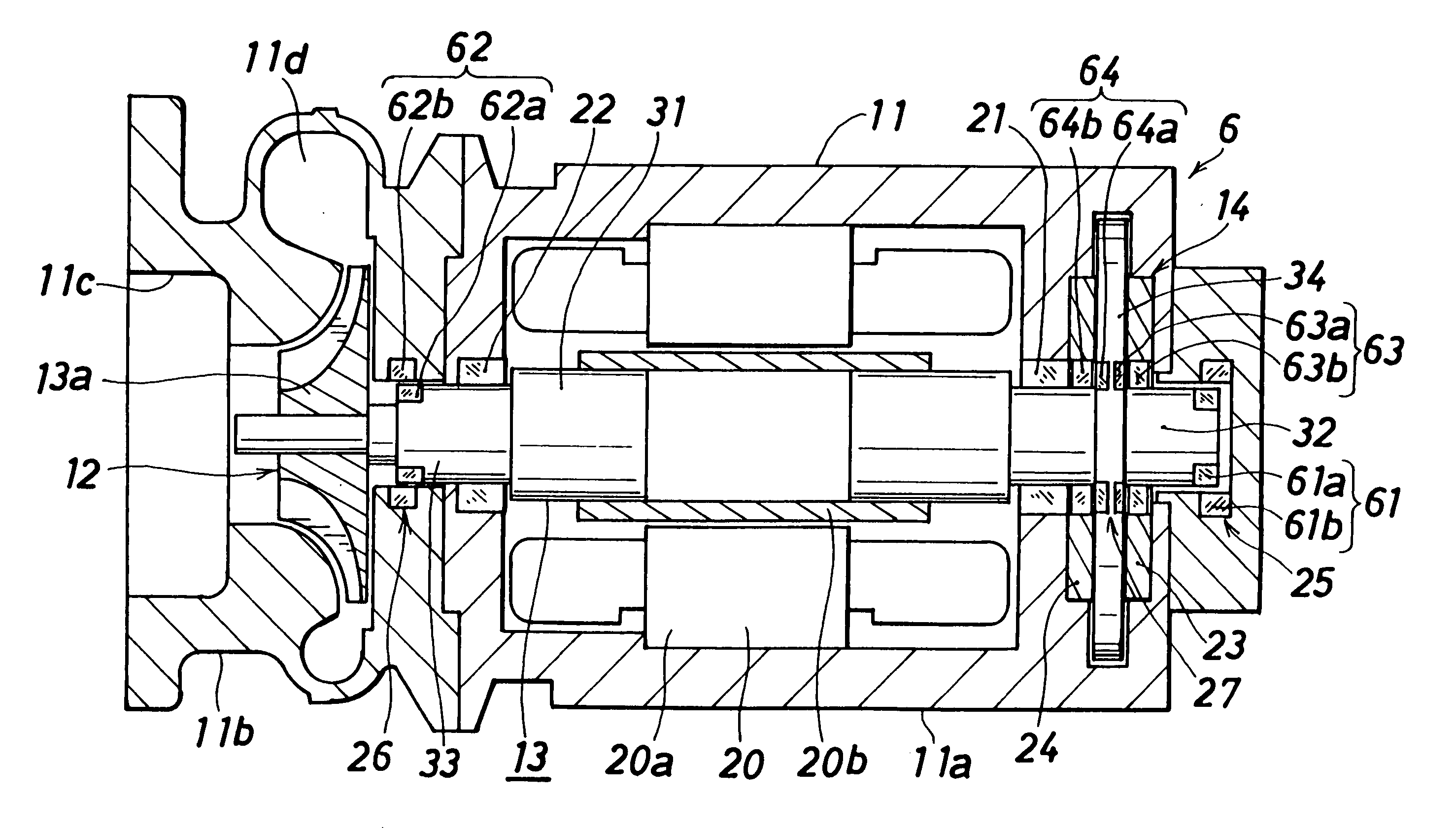
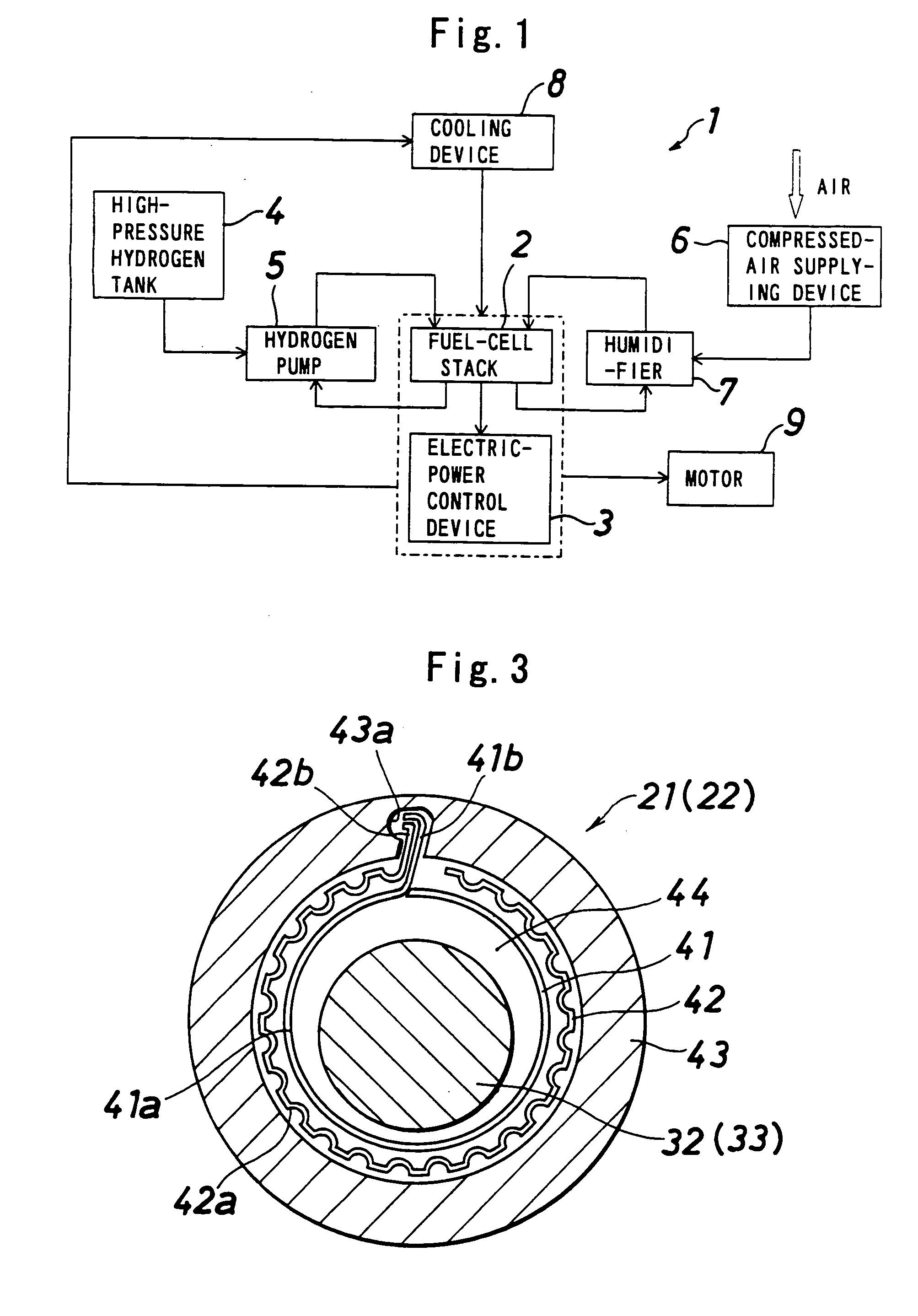
[0025]FIG. 1 illustrates a fuel-cell apparatus to be mounted in a vehicle which employs a fuel-cell compressed-air supplying device according to the present invention. The fuel-cell apparatus (1) includes a fuel-cell stack (2), an electric-power control device (3) which controls the electric power supplied from the fuel-cell stack (2), a high-pressure hydrogen tank (4) and a hydrogen pump (5) which supply hydrogen to the fuel-cell stack (2), a compressed-air supplying device (6) which supplies compressed air to the fuel-cell stack (2), a humidifier (7) which humidifies the compressed air supplied from the compressed-air supplying device (6), and a cooling device (8) which cools the fuel-cell stack (2) and the electric-power control device (3), wherein a motor (9) for r...


PUM


Abstract

A fuel-cell compressed-air supplying device 6 includes a centrifugal compressor 12 provided in a casing 11 and a bearing device 14 for supporting a rotation shaft 13 of the compressor 12. The bearing device 14 includes a pair of radial foil bearings 21 and 22 provided coaxially with the rotation shaft 13 for supporting the rotation shaft 13 in the radial direction, a pair of axial foil bearings 23 and 24 facing to the rotation shaft 13 in the axial direction for supporting the rotation shaft 13 in the axial direction, and a secondary bearing means 25 which is constituted by a combination of plural permanent magnets 61a, 61b, 62a, 62b, 63a, 63b, 64a and 64b and holds the rotation shaft 13 in a non-contact manner at static states.

Description

BACKGROUND OF THE INVENTION [0001] The present invention relates to a fuel-cell compressed-air supplying device installed at an oxygen-supply side in a fuel-cell apparatus which creates energy from hydrogen and oxygen, and for supplying compressed air to the fuel-cell. In particular, the present invention relates to a fuel-cell compressed-air supplying device suitably mounted to a fuel-cell vehicle. [0002] Prototypes of fuel-cell vehicles which incorporate fuel-cells for running have been already fabricated, and Patent Literature 1 (JP-A No. 2002-70762) suggests a fuel-cell vehicle incorporating a scroll compressor as a device suitable for supplying compressed air to the fuel-cells in the fuel-cell vehicle. [0003] In fuel-cell apparatuses for use in fuel-cell vehicles, it has become a critical challenge to reduce the sizes, costs and weights of the fuel-cell apparatuses, and there has also been a need for further reducing the sizes of the compressed-air supplying devices. [0004] The...

Claims


Application Information

Patent Timeline
IPC IPC(8): H02K7/09F16C32/06F04B17/00
CPCF04D29/057F04D29/058F16C2360/42F16C32/0402F16C39/066F16C17/024F16C2380/26
Inventor TANIGUCHI, MANABUMIYAGAWA, YASUKATAUEYAMA, HIROCHIKA
Owner JTEKT CORP
Why Eureka
Try Eureka