Fuel-cell compressed-air supplying device

a technology of compressed air and supplying device, which is applied in the direction of liquid fuel engines, sliding contact bearings, machines/engines, etc., can solve the problems of achieve the effects of reducing the size of the compressed air supplying device, reducing the fatigue life of the bearing, and improving durability

Inactive Publication Date: 2007-07-19
JTEKT CORP
View PDF14 Cites 30 Cited by
  • Summary
  • Abstract
  • Description
  • Claims
  • Application Information

AI Technical Summary

Benefits of technology

[0014]By the presence of this radial attraction-force generating portion, a restraint force acts in a direction that an eccentric rotation of the rotation shaft is restored to a coaxial state, which can reduce the floating revolution number of the radial foil bearing and can improve the durability.
[0015]With the fuel-cell compressed-air supplying device according to the present invention, the rotation shaft is supported in the radial direction by the radial foil bearings (dynamic-pressure gas bearings) and in the axial direction by the control-type axial magnetic bearing, which can suppress the reduction of the fatigue life of the bearings due to high-speed rotation and also can eliminate the necessity of providing the function of circulating lubricating oil, thereby enabling the reduction of the size of the compressed-air supplying device. Furthermore, the axial electromagnets of the axial magnetic bearing are integrated with the radial foil bearings, respectively, which can shorten the length in the axial direction, can achieve high-speed rotation and can further reduce the size.

Problems solved by technology

In fuel-cell apparatuses for use in fuel-cell vehicles, it has become a critical challenge to reduce the sizes, costs and weights of the fuel-cell apparatuses, and there has also been a need for further reducing the sizes of the compressed-air supplying devices.
However, such a centrifugal compressor causes a significant variation in the axial forces which act on the impeller, thereby causing the challenge to ensure the durability of the bearing device of the centrifugal compressor.

Method used


Image

  • Fuel-cell compressed-air supplying device
  • Fuel-cell compressed-air supplying device
  • Fuel-cell compressed-air supplying device

Examples


Embodiment Construction

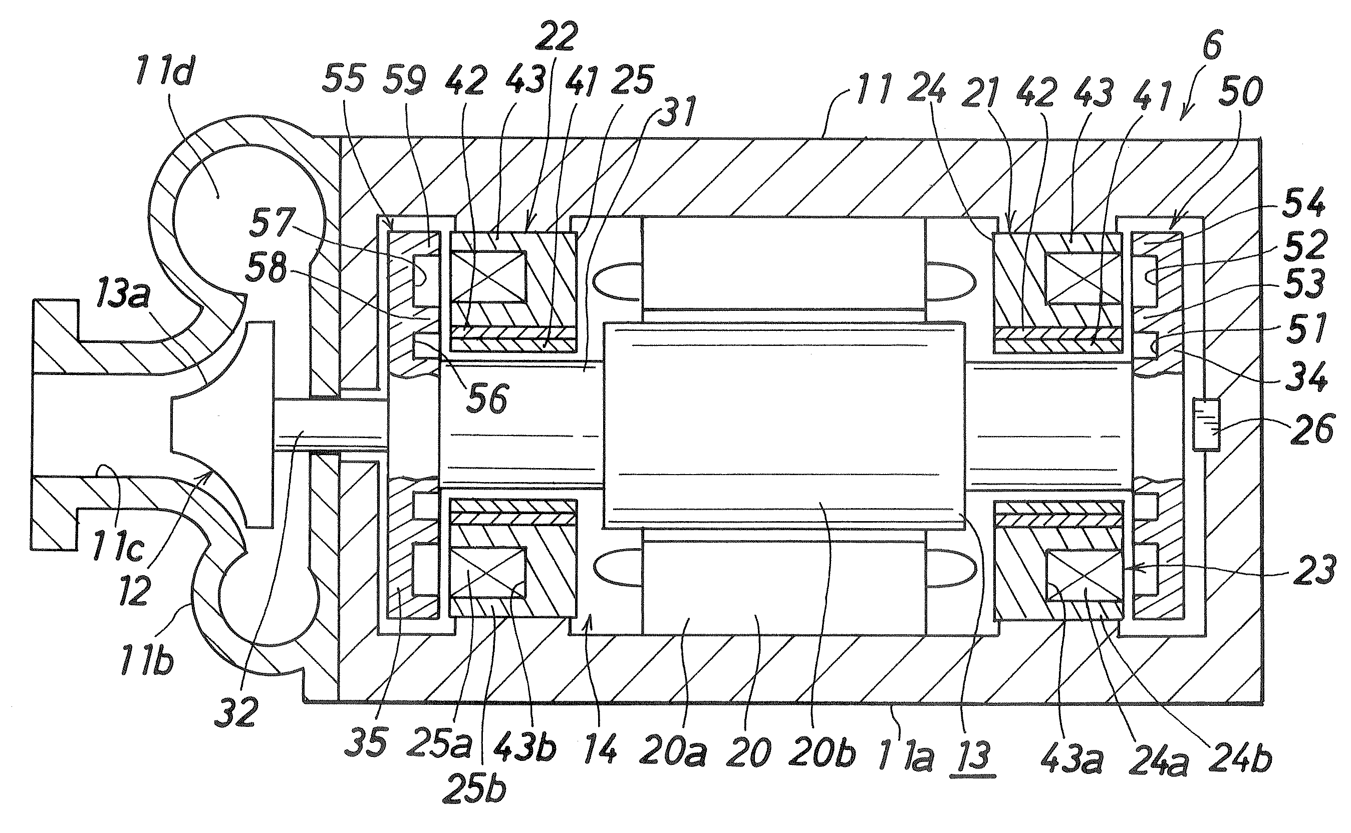
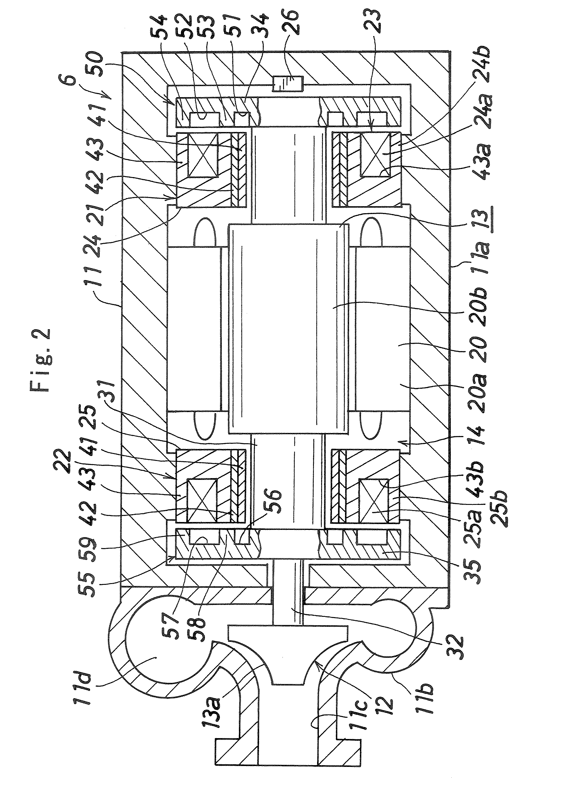
[0023]There will be described embodiments of the present invention, with reference to the drawings. In the following description, the right and the left in FIG. 2 will be designated as front and back, respectively.

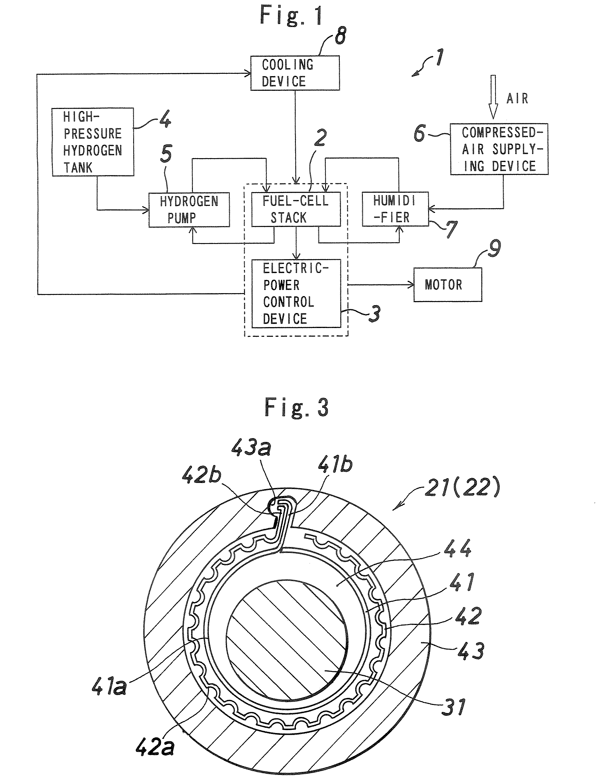
[0024]FIG. 1 illustrates a fuel-cell apparatus to be mounted in a vehicle which employs a fuel-cell compressed-air supplying device according to the present invention. The fuel-cell apparatus (1) includes a fuel-cell stack (2), an electric-power control device (3) which controls the electric power supplied from the fuel-cell stack (2), a high-pressure hydrogen tank (4) and a hydrogen pump (5) which supply hydrogen to the fuel-cell stack (2), a compressed-air supplying device (6) which supplies compressed air to the fuel-cell stack (2), a humidifier (7) which humidifies the compressed air supplied from the compressed-air supplying device (6), and a cooling device (8) which cools the fuel-cell stack (2) and the electric-power control device (3), wherein a motor (9) for runni...


PUM


Abstract

A fuel-cell compressed-air supplying device 6 includes a centrifugal compressor 12 provided in a casing 11, and a bearing device 14 for supporting a rotation shaft 13 of the compressor 12. The bearing device 14 includes a pair of radial foil bearings 21 and 22 provided coaxially with the rotation shaft 13 for supporting the rotation shaft 13 in the radial direction, and an axial magnetic bearing 23 facing to the rotation shaft 13 in the axial direction for supporting the rotation shaft 13 in the axial direction. Axial electromagnets 24 and 25 of the axial magnetic bearing 23 are integrated with the radial foil bearings 21 and 22, respectively.

Description

BACKGROUND OF THE INVENTION[0001]The present invention relates to a fuel-cell compressed-air supplying device installed at an oxygen-supply side in a fuel-cell apparatus which creates energy from hydrogen and oxygen, and for supplying compressed air to the fuel-cell. In particular, the present invention relates to a fuel-cell compressed-air supplying device suitably mounted to a fuel-cell vehicle.[0002]Prototypes of fuel-cell vehicles which incorporate fuel-cells for running have been already fabricated, and Patent Literature 1 (JP-A No. 2002-70762) suggests a fuel-cell vehicle incorporating a scroll compressor as a compressed-air supplying device suitable for supplying compressed air to the fuel-cells in the fuel-cell vehicle.[0003]In fuel-cell apparatuses for use in fuel-cell vehicles, it has become a critical challenge to reduce the sizes, costs and weights of the fuel-cell apparatuses, and there has also been a need for further reducing the sizes of the compressed-air supplying ...

Claims


Application Information

Patent Timeline
Patent Type & Authority Applications(United States)
IPC IPC(8): H02K7/09F16C32/06F16C33/22
CPCF04D29/05F16C17/024F16C2360/44F16C32/0476F16C2360/42F16C32/0402
Inventor TANIGUCHI, MANABUUEYAMA, HIROCHIKAMIYAGAWA, YASUKATA
Owner JTEKT CORP
Why Eureka
Try Eureka