Lightening device for metal halide discharge lamp

a technology of metal halide discharge and lighting device, which is applied in the direction of energy-saving lighting, transportation and packaging, lighting and heating equipment, etc., can solve the problems of low lamp efficiency, increased current capacity in the related facilities, and increased electrode loss

Inactive Publication Date: 2007-03-29
HARISON TOSHIBA LIGHTING CORP
View PDF7 Cites 7 Cited by
  • Summary
  • Abstract
  • Description
  • Claims
  • Application Information

AI Technical Summary

Benefits of technology

[0044] A main object of the present invention is to provide a metal halide discharge lamp which essentially permits disusing mercury, which is harmful to the living environment of the human being, and which also permits obtaining electrical characteristics and light-emitting characteristics substantially equal to those produced by a metal halide discharge lamp in which is sealed mercury, to provide a lighting device for the particular metal halide discharge lamp, and to provide an illumination apparatus using the particular metal halide discharge lamp.
[0045] An auxiliary object of the present invention is to provide a metal halide discharge lamp which permits a good rising of chromaticity at the start-up time, which permits light control for the dimming purpose, which is small in unevenness of the characteristics, which permits an instant re-start up easily, and which is effective for preventing the hermetic vessel from being ruptured, to provide a lighting device for the particular metal halide discharge lamp, and to provide an illumination apparatus using the particular metal halide discharge lamp.
[0046] Another auxiliary object of the present invention is to provide a metal halide discharge lamp in which mercury is not sealed, which is small in heat loss, and which is effective for preventing the light emitting efficiency from being lowered, to provide a lighting device for the particular metal halide discharge lamp, and to provide an illumination apparatus using the particular metal halide discharge lamp.

Problems solved by technology

In this case, problems are brought about that the current capacities are increased in the related facilities such as the lighting device, illuminating device and wiring.
On the other hand, where the lamp current is unduly high, the electrode loss is increased, leading to a low lamp efficiency.
As a result, if the lamp voltage is unduly low, the lamp current must be increased for making up for the low lamp voltage, with the result that the electrode loss is increased in proportion to the lamp current so as to lower the lamp efficiency.
In other words, the greatest problem inherent in the conventional metal halide discharge lamp is that mercury is sealed in the lamp.
In addition, many problems remain unsolved when it comes to the metal halide discharge lamp in which mercury is sealed for obtaining a desired lamp voltage, as pointed out below:
However, since mercury is rapidly evaporated in the switch-on time, mercury takes much energy so as to cause delay in the rising of the vapor pressure of a light-emitting metal.
It should be noted that the light emitted from mercury is poor in color characteristics and in color rendering properties.
Since the rising of the spectral characteristics is very poor as described above, it takes a long time to obtain emission of light having desired spectral characteristics.
Since the vapor pressure of a halide of a light-emitting metal is markedly lower than that of mercury, a change in temperature of the light emitting tube causes a change in the evaporation amount of the halide, leading to a change in the vapor pressure within the lamp.
As a result, the color temperature of the emitted light is lowered, leading to poor color rendering properties.
This indicates that the conventional metal halide discharge lamp, which requires mercury sealing, is unsuitable for the light control (dimming).
However, the color characteristics are markedly impaired in the conventional metal halide discharge lamp requiring the mercury sealing.
The metal halide discharge lamps having mercury sealed therein are uneven in temperature of the light emitting tubes, which are caused by unevenness in the size of the individual lamps.
As a result, unevenness in the characteristics tends to be brought about even under the same input power.
These difficulties tend to bring about a problem particularly where a plurality of metal halide discharge lamps are used in combination for illumination as in, for example, shops.
It follows that the lighting circuit is rendered costly.
Since the mercury vapor pressure is very high during the lighting as described previously, strain of the lamp is increased during lighting of the lamp over a long period of time, with the result that the lamp tends to be ruptured.
The problem of rupture markedly lowers the reliability of the lamp.
As a result, the arc temperature is distributed to depict a parabola, making it difficult to narrow the arc.
In this case, however, convection occurs vigorously if the lighting pressure of mercury is high, with the result that the arc is rendered unstable.
It follows that it is impossible to put this technique to practical use.
However, it is practically difficult to permit a metal halide discharge lamp of the construction similar to that of the conventional lamp to withstand the high pressure within the lamp during the lighting of the lamp.
It follows that the hermetic vessel widely used in the conventional lamp fails to obtain a high reliability in respect of the measure against rupture of the hermetic vessel.

Method used


Image

  • Lightening device for metal halide discharge lamp
  • Lightening device for metal halide discharge lamp
  • Lightening device for metal halide discharge lamp

Examples


embodiment 1

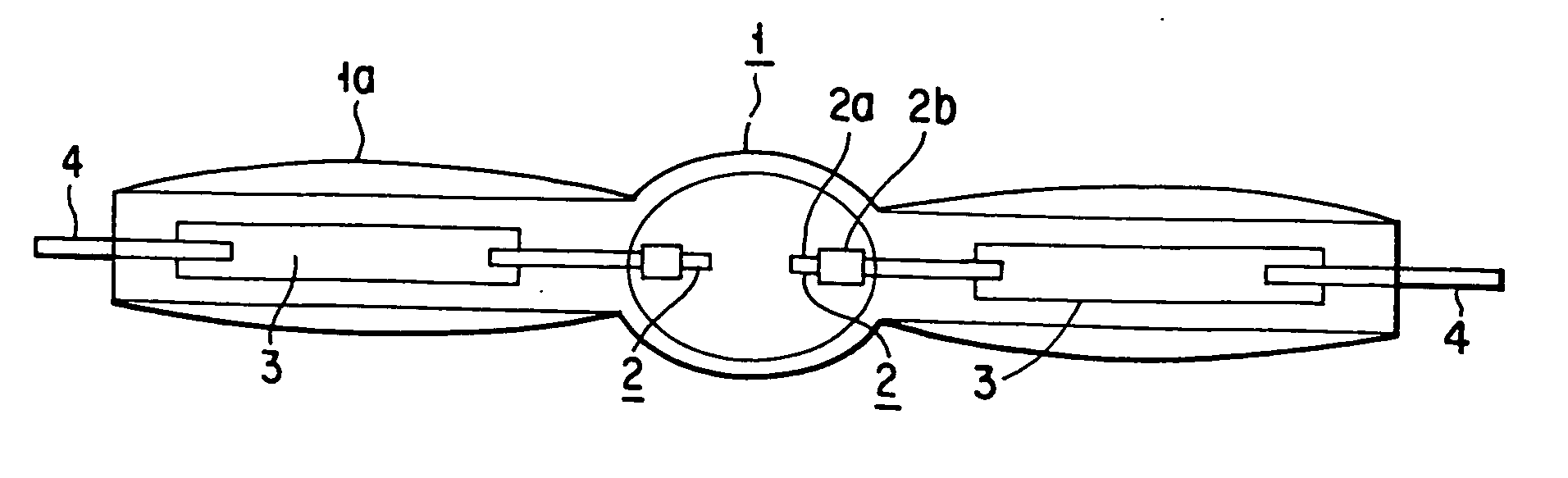
[0189]FIG. 3 is a front view showing a metal halide discharge lamp according to the first embodiment of the present invention. As shown in the drawing, the discharge lamp comprises a hermetic vessel 1, a pair of electrodes 2, metal foils 3 for the sealing, and outer lead wires 4. The metal halide discharge lamp of this embodiment is of a short arc type.

[0190] The hermetic vessel 1 is prepared by rotating under heat a quartz glass tube having an inner diameter of 14 mm into a bulb having an elliptical cross section. A pair of slender sealing portions 1a, 1a are integrally fixed to the ends in the long axis direction of the elliptical hermetic vessel 1.

[0191] The electrode 2 comprises an electrode shaft 2a and an electrode coil 2b. The tip portion of the electrode shaft 2a somewhat projects inward and, the electrode coil 2b is wound about the projecting tip portion of the electrode shaft 2a. The proximal end portion of the electrode shaft 2a is welded to one end of the sealed metal ...

embodiment 2

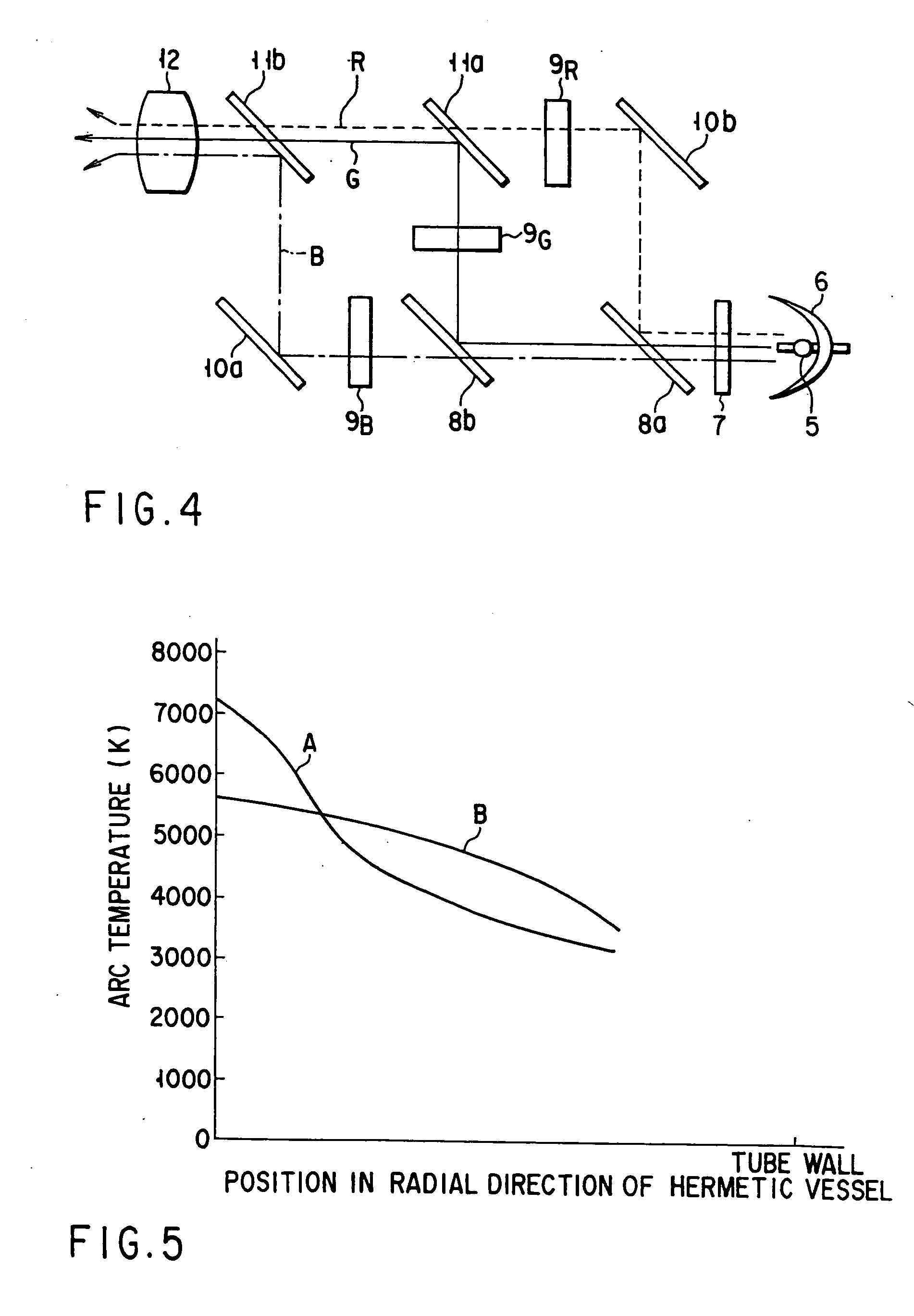
[0207]FIG. 7 schematically shows a liquid crystal projector as a first embodiment of the illumination apparatus of the present invention. The discharge lamp for the projector shown in FIG. 6 is used in the liquid crystal projector shown in FIG. 7. The reference numerals common with FIGS. 6 and 7 represent the same members of the projector and, thus, reference thereto is omitted in the following description.

[0208] As shown in the drawing, the liquid crystal projector comprises a liquid crystal display means 11, an image control means 12, an optical system 13, a body case 14, and a screen 15. The liquid crystal display means 11 serves to display the image to be displayed by utilizing a liquid crystal material. To be more specific, the liquid crystal display means 11 is irradiated with light emitted from behind the display means 11 by the metal halide discharge lamp 5 included in the metal halide discharge lamp apparatus and collected by the reflector 6. The image control means 12 ser...

embodiment 3

[0209]FIG. 8 is a cross sectional view, or front view, showing a metal halide discharge lamp according to a second embodiment of the present invention. The reference numerals common with FIGS. 3 and 8 denote the same members of the discharge lamp and, thus, reference thereto is omitted in the following description.

[0210] The metal halide discharge lamp of the second embodiment is also of a short arc type, and differs from the discharge lamp of the first embodiment in that, in the second embodiment, the inner volume of the hermetic vessel 1 is as small as 0.05 cc. It should also be noted that, in the second embodiment, the hermetic vessel 1 has an inner diameter of 4 mm. An electrode coil is not wound about the electrode 2. Further, the distance between the two electrodes is 4.2 mm.

[0211] The discharge medium used in the second embodiment consisted of a xenon gas sealed at 1 atmosphere, a first halide including scandium iodide (ScI3) sealed in an amount of 0.14 mg and sodium iodide...


PUM


Abstract

A metal halide discharge lamp with which essentially permits disusing mercury is provided. The metal halide discharge lamp comprises a refractory and transparent hermetic vessel, a pair of electrodes fixed to the hermetic vessel, and a discharge medium sealed in the hermetic vessel and containing a first halide, a second halide, and a rare gas. The first halide is a halide of metal which achieves a desired light emission. The second halide has a relatively high vapor pressure, being at least one halide of metal which is unlikely to emit a visible light compared with the metal of the first halide and acts as a buffer gas.

Description

BACKGROUND OF THE INVENTION [0001] The present invention relates to a metal halide discharge lamp, a lighting device for a metal halide discharge lamp, and an illuminating apparatus using a metal halide discharge lamp. [0002] A metal halide discharge lamp comprises a light-emitting tube provided with a pair of electrodes arranged to face each other. A rare gas, a halide of a light-emitting metal, and mercury are sealed in the light-emitting tube to form the metal halide discharge lamp. The discharge lamp of the particular construction exhibits a relatively high efficiency and high color rendering properties and, thus, is used widely. [0003] The metal halide discharge lamp is classified into a short arc type and a long arc type. The short arc type metal halide discharge lamp is used in projectors such as a liquid crystal projector in which light rays emitted from a lamp are collected so as to be projected onto a screen, and an overhead projector, and is also used for illumination of ...

Claims


Application Information

Patent Timeline
Patent Type & Authority Applications(United States)
IPC IPC(8): H01J61/20H01J17/20
CPCF21S48/1241H01J61/125H01J61/302Y02B20/46H05B37/0218H05B41/2886Y02B20/202H01J61/86F21S41/24F21S41/645H05B47/11Y02B20/00Y02B20/40
Inventor ISHIGAMI, TOSHIHIKOSAITA, KIYOSHIMATSUDA, MIKIOHIRUTA, TOSHIO
Owner HARISON TOSHIBA LIGHTING CORP
Why Eureka
Try Eureka