Zoom lens
a technology of zoom lens and lens body, applied in the field of zoom lens, can solve the problems of insufficient proportion of plastic lens used in constituent lenses to achieve cost reduction, and achieve the effects of reducing thickness, preventing reflection, and compact incorporation
- Summary
- Abstract
- Description
- Claims
- Application Information
AI Technical Summary
Benefits of technology
Problems solved by technology
Method used
Image

Examples
example 1
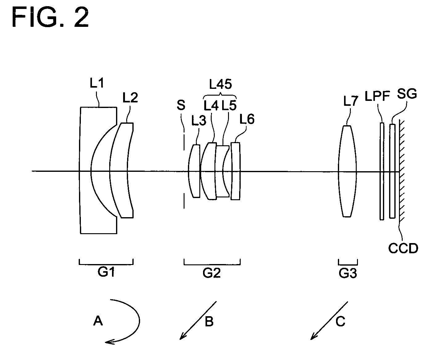
[0081] Table 1 shows the lens data of the zoom lens of Example 1. FIG. 2 is a cross sectional view of the zoom lens of Example 1. FIGS. 3(A)-1 through 3(C)-3 show the aberration curve of the spherical aberration, astigmatism and distortion of the zoom leng of Example 1. FIGS. 3(A)-1 through 3(A)-3 indicate the aberration curves on the wide-angle end. FIGS. 3(B)-1 through 3(B)-3 show intermediate aberration curves. FIGS. 3(C)-1 through 3(C)-3 represent the aberration curves for the telephoto end. In the following aberration curves, a solid line indication line d, and a dot denotes line g for spherical aberration curves. For aspherical aberration curves, a solid line indicates a sagittal image surface and a dot indicates a meridional image surface.
TABLE 1Example 1rdndνd1−1310.5121.2 1.52556.0*124.9121.9237.3051.831.60727.1*2413.166A59.3531.181.81646.66−598.0230.1575.2781.451.72954.7816.9980.8 1.84723.894.1520.9610 −19.2880.8 1.52556.0*311 −20.436B12 14.321.811.52556.0*413 −23.213C14...
example 2
[0084] Table 2 shows the lens data of the zoom lens of Example 2. FIG. 4 is a cross sectional view of the zoom lens of Example 2. FIGS. 5(A)-1 through 5(C)-3 represent the aberration curves for spherical aberration, astigmatism, and distortion of the zoom lens of Example 2. FIGS. 5(A)-1 to 5(A)-3 shows the aberration curves on the wide-angle end. FIGS. 5(B)-1 through 5(B)-3 indicate intermediate aberration curves. FIGS. 5(C)-1 through 5(C)-3 show aberration curves on the telephoto end.
TABLE 2Example 2rdndνd1138.05941.201.52556.0*124.8837691.8737.2823161.831.60727.1*2412.94338A59.0786521.181.81646.662104.7130.1575.3829171.451.72954.7818.102090.801.84623.894.2005010.9610 −18.565560.801.52556.0*311 −20.20602B12 15.808631.811.52556.0*413 −19.58778C14 ∞0.391.54866.715 ∞0.6716 ∞0.501.51664.117 ∞1st surface2nd surfaceκ0.0000E+00κ−2.0284E−01A43.3634E−04A4−6.8085E−05A6−4.5850E−06A69.9552E−06A8−1.7208E−07A8−2.1839E−07A103.8682E−09A10−6.1996E−08A12−1.5740E−11A12−1.3003E−09A146.5609E−113rd su...
example 3
[0087] Table 3 shows the lens data of the zoom lens of Example 3. FIG. 6 is a cross sectional view of the zoom lens of Example 3. FIGS. 7(A)-1 through 7(C)-3 represent the aberration curves for spherical aberration, astigmatism, and distortion of the zoom lens of Example 3. FIGS. 7(A)-1 to 7(A)-3 shows the aberration curves on the wide-angle end. FIGS. 7(B)-1 through 7(B)-3 indicate intermediate aberration curves. FIGS. 7(C)-1 through 7(C)-3 show aberration curves on the telephoto end.
TABLE 3Example 3rdndνd1−117.32540.801.52556.0*124.7548310.8136.0398540.981.52556.0*245.239531.0957.8334251.471.60727.1*3620.44105A79.6937161.201.88340.88210.69290.2095.3592571.501.73054.71030.405480.901.84723.8114.1564211.0012−17.357940.901.52556.0*413−14.34706B1419.591191.701.52556.0*515−12.83547C16∞0.391.54866.717∞0.6718∞0.501.51664.119∞2nd surface4th surfaceκ−8.9970E−01κ0.0000E+00A46.6468E−04A4−2.5108E−04A61.9894E−05A6−4.3875E−05A87.4559E−07A8−1.3435E−06A101.8635E−08A10−4.3985E−09A12−3.3158E−09A12...
PUM
 Abstract
Description
Claims
Application Information
 - Generate Ideas
- Intellectual Property
- Life Sciences
- Materials
- Tech Scout
- Unparalleled Data Quality
- Higher Quality Content
- 60% Fewer Hallucinations
Browse by: Latest US Patents, China's latest patents, Technical Efficacy Thesaurus, Application Domain, Technology Topic, Popular Technical Reports.
© 2025 PatSnap. All rights reserved.Legal|Privacy policy|Modern Slavery Act Transparency Statement|Sitemap|About US| Contact US: help@patsnap.com