
Information recording method, information recording apparatus and information recording medium

a technology of information recording and recording medium, which is applied in the field of information recording method, information recording apparatus and information recording medium, can solve the problems of inability to form a recording mark having an even mark width, and achieve the effects of high density, favorable overwriting property, and high speed

Inactive Publication Date: 2007-03-29
PANASONIC CORP
View PDF15 Cites 16 Cited by
  • Summary
  • Abstract
  • Description
  • Claims
  • Application Information

AI Technical Summary

Benefits of technology

"The present invention provides an information recording method and apparatus for forming a recording mark and a space on an information recording medium by irradiating a pulse train onto the medium while rotating it at a certain linear velocity. The method includes determining the power level of the first pulse in accordance with the linear velocity and the power level of the second pulse. This allows for the formation of a recording mark with an appropriate shape and width, even when recording at a high speed. The technical effect of this invention is to improve the quality of recording / reproduction signals by forming a recording mark with an appropriate shape and width, regardless of the recording linear velocity."

Problems solved by technology

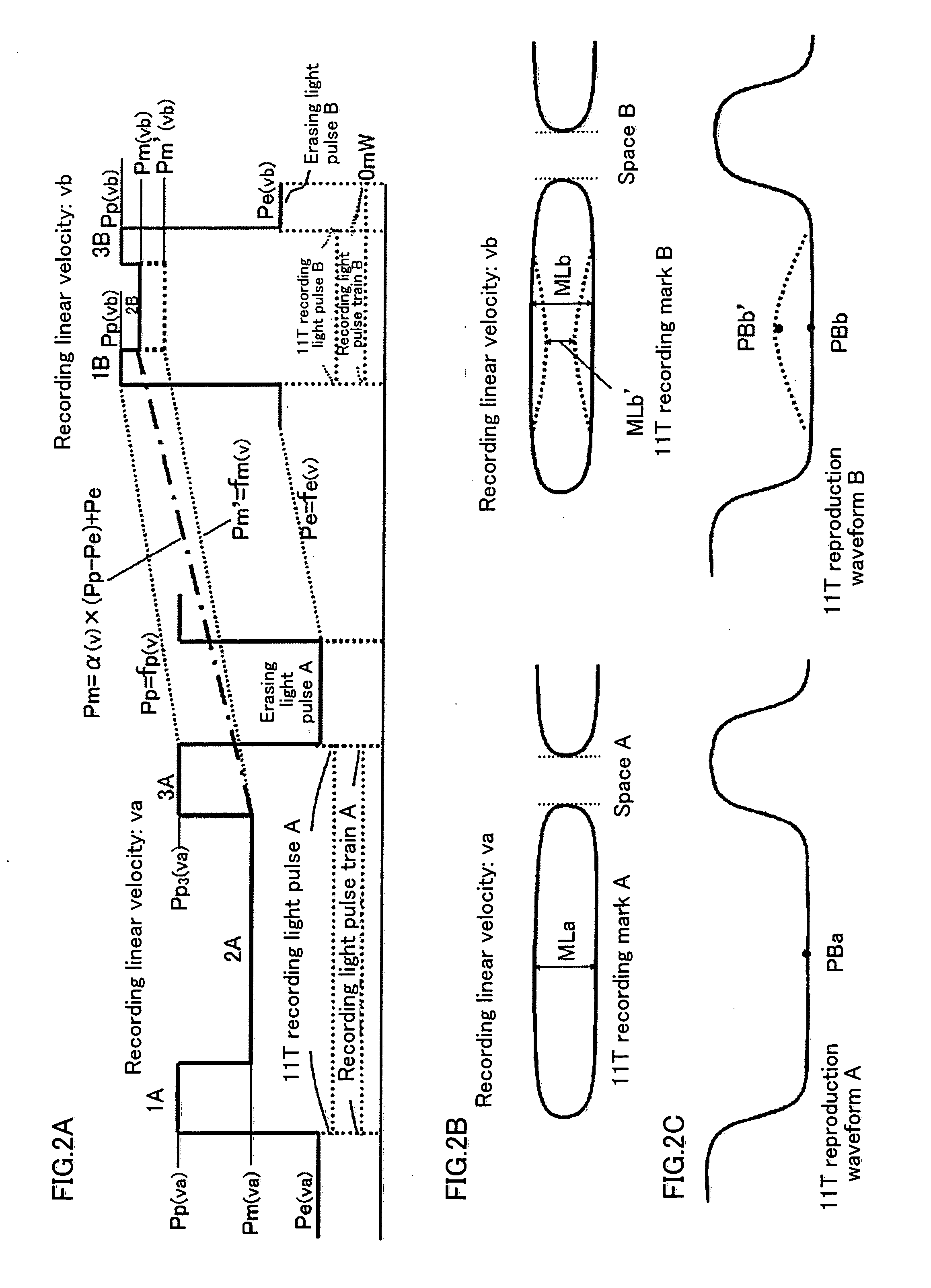
However, in a case where information is recorded at a constant angular velocity (CAV) at a high density and a high speed (e.g. in a case where information is recorded on a DVD-RAM), it is impossible to form a recording mark having an even mark width, even if the recording power level of each of two or more types of pulses is defined by a continuous function having only the recording linear velocity as variable.

Method used


Image

  • Information recording method, information recording apparatus and information recording medium
  • Information recording method, information recording apparatus and information recording medium
  • Information recording method, information recording apparatus and information recording medium

Examples


Embodiment Construction

[0071] Hereinafter, the embodiments of the present invention will be described below with reference to the drawings.

1. Structure of an Information Recording Apparatus 100

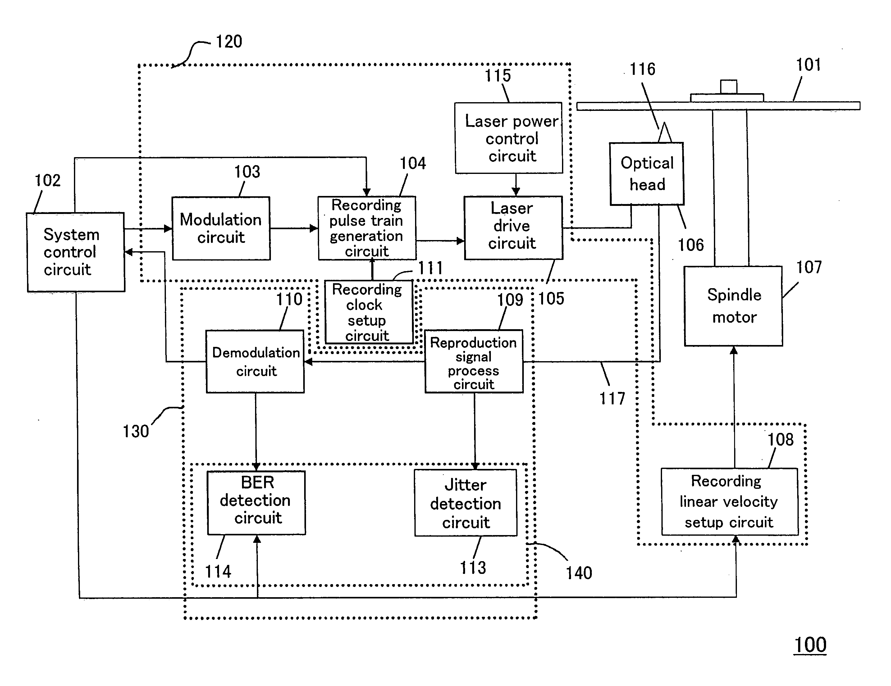
[0072]FIG. 1 shows a structure of an information recording apparatus 100 according to an embodiment of the present invention.

[0073] The information recording apparatus 100 is constructed to be inserted with an information recording medium 101 (hereafter, optical disc 101) for recording and / or reproducing data.

[0074] The information recording apparatus 100 includes an optical head 106, a spindle motor 107, a system control circuit 102, a recording system section 120, and a reproduction system section 130.

[0075] The system control circuit 102 controls the operation of all the components included in the information recording apparatus 100. The optical head 106 converges the light of the semiconductor laser and irradiates the converged light onto the optical disc 101. The spindle motor 107 drives the optical disc 1...


PUM

PropertyMeasurementUnit
linear velocityaaaaaaaaaa
power levelaaaaaaaaaa
lengthaaaaaaaaaa

Abstract

An information recording method capable of properly forming a width of a central portion of a recording mark, an information recording apparatus and an information recording medium are provided. The present invention includes the steps of generating a pulse train including a first pulse and a second pulse and forming at least one of a recording mark and a space onto an information recording medium by irradiating the pulse train onto the information recording medium while rotating the information recording medium at a certain linear velocity. The first pulse is a pulse for forming a central portion of the recording mark, among the recording mark and the space. The second pulse is a pulse for forming a portion other than the central portion of the recording mark, among the recording mark and the space. The step of generating the pulse train includes a step of determining a power level of the first pulse in accordance with the linear velocity and a power level of the second pulse.

Description

TECHNICAL FIELD [0001] The present invention relates to an information recording method and an information recording apparatus for forming at least one of a recording mark and a space onto an information recording medium by irradiating pulse train onto the information recording medium while rotating the information recording medium at a certain linear velocity, and an information recording medium having predetermined information recorded thereon. [0002] The present invention is, for example, utilized in a case where information is recorded on the information recording medium at a constant angular velocity (CAV) while maintaining a recording linear density almost constant by varying a recording clock in accordance with the changes in linear velocity. BACKGROUND ART [0003] When information is recorded onto an information recording medium (e.g. an optical disc) at a constant angular velocity (CAV), it is important to optimize a recording power level of the recording light pulse train f...

Claims


Application Information

Patent Timeline
Patent Type & Authority Applications(United States)
IPC IPC(8): G11B7/0045G11B20/10G11B7/006G11B7/125
CPCG11B7/0062G11B7/00456G11B7/0045G11B7/1263
Inventor KOISHI, KENJI
Owner PANASONIC CORP
Learn More