
Septic system

Active Publication Date: 2007-03-29
CUR TECH LLC
View PDF27 Cites 0 Cited by
  • Summary
  • Abstract
  • Description
  • Claims
  • Application Information

AI Technical Summary

Benefits of technology

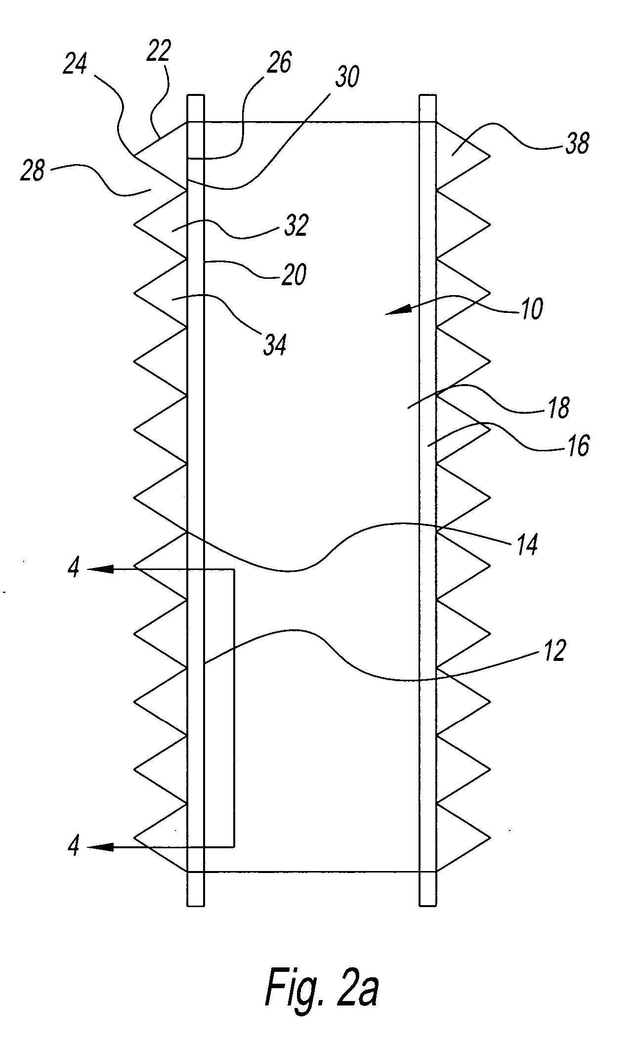
[0010] It is another object of the present invention to provide a septic system that can be connected in a modular fashion to an existing septic system.
[0011] It is yet another object of the present invention to provide a septic system that increases a surface area on a lateral side of an existing septic system.
[0014] It is a further object of the present invention to provide a septic system that has a baffling arrangement on a lateral side for an improved interface with ground.
[0015] It is a further object of the present invention to provide a septic system that has a triangular baffling arrangement on a lateral side of an existing system for an improved interface with sand.

Problems solved by technology

Such septic systems are deficient in their operation.
First of all, zoning ordinances for certain sized homes require larger septic systems.
Such larger septic systems may not fit on the desired building lot.
This can be problematic under certain circumstances because the desired septic system may not fit in a certain lot and the new home owner may be limited to only a second sized septic system that is less than desired.
Secondly, in other circumstances homeowners may wish to expand the capacity of the septic system in a retrofit manner from a first size to another second size to accommodate a larger home.
However, a known problem in the art is that the under this arrangement, the second sized larger septic system like Nichols' leaching system will require the homeowner to excavate the leaching system and remove the leaching system.

Method used


Image

  • Septic system
  • Septic system
  • Septic system

Examples


Embodiment Construction

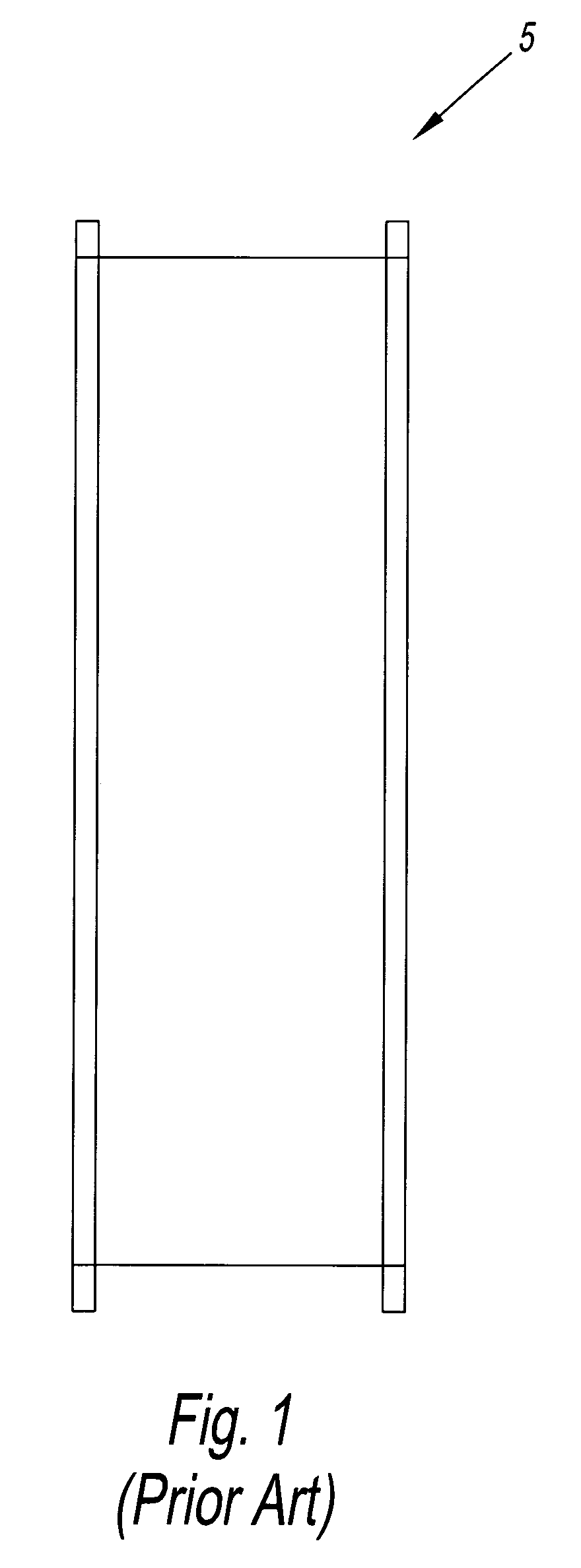
[0023] Referring to FIG. 1, there is shown a septic gallery 5 as is known in the art. The septic gallery 5 is preferably a container that is placed in a leaching field, such as ground or sand, and is utilized for drainage of effluent. Effluent is a term commonly used for waste materials such as liquid and solid industrial refuse or liquid and solid residential sewage that flows out of a source and is discharged into the environment. The effluent is carried from a source such as a bathroom to the septic tank, then to the leaching field for dispersion, diffusion, or percolation, into surrounding soil.

[0024] Known pipes carry the effluent discharge and release the material into a chamber, or vault such as the septic gallery 5. The gallery 5 as is known will have a number of perforation or holes leading from the septic gallery 5. The gallery 5 is usually buried in a trench to facilitate dispersion of the effluent into the soil. All of the solid effluent stays in the septic tank, and on...


PUM

PropertyMeasurementUnit
Areaaaaaaaaaaa
Dimensionaaaaaaaaaa
Resilienceaaaaaaaaaa

Abstract

A modular appendage for a septic gallery has a first modular section for connection to a lateral side of the gallery with the first modular section having a number of apertures thereon. The first modular section has a first area. The lateral side of the septic gallery has a second area. The first area is greater than the second area for increased drainage and thus adds capacity to the gallery.

Description

BACKGROUND OF THE INVENTION [0001] 1. Field of the Invention [0002] The present invention relates to a septic system for handling household waste water. More particularly, the present invention relates to a septic system that can expand the amount of filtering material around or adjacent to a conventional new or existing septic gallery to expand a septic gallery capacity. [0003] 2. Description of the Related Art [0004] Septic systems are well known in the art. One such septic system is disclosed in U.S. Pat. No. 4,759,661 to Nichols, et al. (hereinafter “Nichols”). Nichols discloses a leaching system conduit made from a thermoplastic member having lateral sidewalls with a number of apertures. The thermoplastic member is an arch shaped member in cross section and has the apertures for the passage of liquid therethrough. The lateral sidewalls also have a number of corrugations formed in a rectangular shaped manner. [0005] Such septic systems are deficient in their operation. First of ...

Claims


Application Information

Patent Timeline
IPC IPC(8): E02B11/00E02B13/00B01D17/00
CPCE03F11/00E03F1/002C02F3/286
Inventor CURRIVAN, FRANK
Owner CUR TECH LLC
Learn More