Thin micro reforming apparatus

a technology of reformer and micro-chip, which is applied in the direction of liquid-gas reaction process, electrochemical generator, chemical/physical/physicochemical process, etc., can solve the problems of difficult miniaturization, inability to achieve miniaturization, so as to reduce the overall heat supply

Inactive Publication Date: 2007-03-29
SAMSUNG ELECTRO MECHANICS CO LTD
View PDF5 Cites 7 Cited by
  • Summary
  • Abstract
  • Description
  • Claims
  • Application Information

AI Technical Summary

Benefits of technology

[0016] The present invention has been made to solve the foregoing problems of the prior art and therefore an object of certain embodiments of the present invention is to provide a thin micro reforming apparatus which allows fuel to absorb heat from a CO remover while passing through a channel of a fuel inlet portion without requiring additional heat supplied to an evaporator, thereby reducing overall heat supply.

Problems solved by technology

However, the method requires a reformer, thus having a disadvantage for miniaturization.
Such a conventional reforming apparatus has a multilayer structure of at least 10 layers, which makes it difficult to achieve miniaturization.
That is, even if each layer is thin, the overall structure is inevitably thick in its volume and the difficulty in bonding the multiple layers hinders mass-production.
This method allows heat exchange but increases overall thickness and exhausts fuel, hindering heat efficiency.
Such a conventional reformer, however, uses a heater 422 to heat up the fuel, consuming a great amount of energy.
In addition, the conventional method yields a large volume with difficult manufacturing processes.
Further, using a silicon substrate and glass, which has high heat conductivity, the method does not facilitate the optimal reaction temperature distribution which requires at least 250° C. maintained in the reforming part, and 190° C. maintained in the CO removing part.

Method used


Image

  • Thin micro reforming apparatus
  • Thin micro reforming apparatus
  • Thin micro reforming apparatus

Examples


Embodiment Construction

[0030] Preferred embodiments of the present invention will now be described in detail with reference to the accompanying drawings.

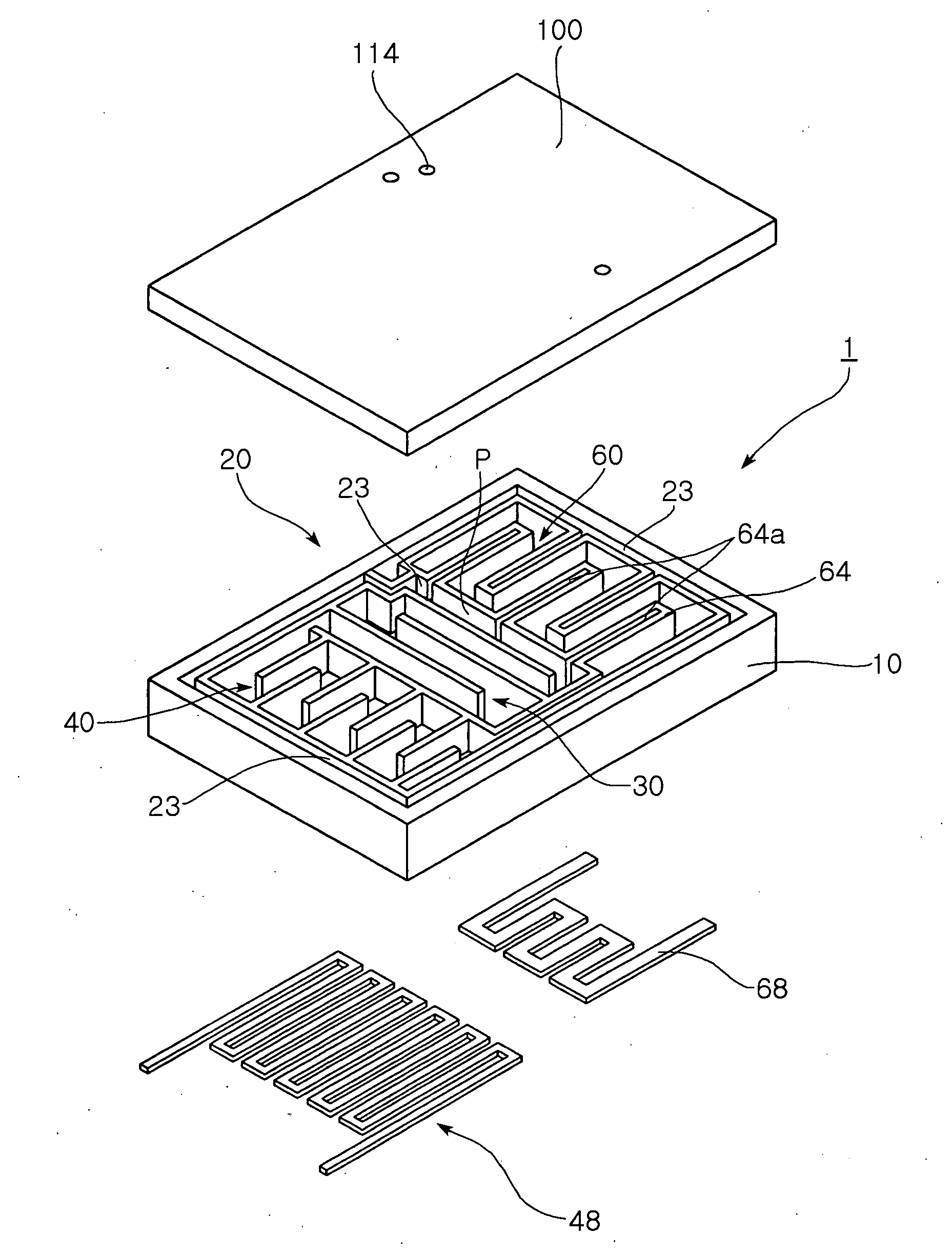
[0031] As shown in FIG. 4, the thin micro reforming apparatus 1 according to a preferred embodiment of the present invention includes a substrate 10 having flow paths formed therein. The substrate 10 may be made of one selected from a group consisting of silicon, metal, glass and heat-resistant plastic. The substrate 10 has a side thereof etched to have recessed flow paths formed therein by partition walls.

[0032] That is, a side of the substrate 10 is etched to be recessed in a desired form of flow paths therein.

[0033] In addition, the substrate 10 has a fuel inlet portion 20 for introducing fuel into the flow paths thereof. As shown in FIGS. 4 and 5, the fuel inlet portion 20 has a structure that allows fuel to flow through a channel which starts from a substantially central portion of the substrate 10 and is extended in a predetermined length, thereb...


PUM


Abstract

The invention relates to a thin micro reforming apparatus used in a fuel cell system. The reforming apparatus includes a substrate having a flow path formed therein, and a fuel inlet portion for introducing fuel to the flow path of the substrate. The fuel inlet portion allows the fuel to flow through a predetermined length of a channel, thereby preheating the fuel. The reforming apparatus also includes an evaporator having a flow path for gasifying liquid fuel, and a reformer for reforming fuel into hydrogen gas via heat absorption reaction. The reforming apparatus further includes a CO remover for removing CO gas contained in the hydrogen gas via heat generation reaction, and a cover for sealing the flow paths of the substrate. The channel of the fuel inlet portion surrounds the evaporator, reformer and CO remover, thereby facilitating insulation at the sides of the reforming apparatus and increasing heat efficiency.

Description

CLAIM OF PRIORITY [0001] This application claims the benefit of Korean Patent Application No. 2005-91321 filed on Sep. 29, 2005, in the Korean Intellectual Property Office, the disclosure of which is incorporated herein by reference. BACKGROUND OF THE INVENTION [0002] 1. Field of the Invention [0003] The present invention relates to a thin micro reformer used in a fuel cell system. More particularly, the invention relates to a thin micro reformer which has a channel extended from a fuel inlet portion, along a periphery of a substrate to allow the fuel to flow therethrough to be preheated and enable heat exchange in a reformer and a CO remover, thereby significantly improving heat efficiency and enabling reformation of the fuel and removal of CO in a single sheet of substrate. [0004] 2. Description of the Related Art [0005] Recently, there have been increased uses of portable small-sized electronic devices including mobile phones, Personal Digital Assistants (PDAs), digital cameras, ...

Claims


Application Information

Patent Timeline
Patent Type & Authority Applications(United States)
IPC IPC(8): B01J10/00B01J8/04
CPCB01B1/005B01J19/0093B01J2219/00783B01J2219/00835B01J2219/00873C01B2203/1294C01B2203/0233C01B2203/044C01B2203/047C01B2203/085C01B3/384Y02E60/50H01M8/06C01B3/38C01B3/26
Inventor GIL, JAE HYOUNGLEE, RO WOONKIM, SUNG HANJANG, JAE HYUK
Owner SAMSUNG ELECTRO MECHANICS CO LTD
Why Eureka
Try Eureka