Apparatus and method of forming an applied film

a technology of applied film and apparatus, which is applied in the direction of photomechanical apparatus, instruments, photosensitive materials, etc., can solve the problems of inability to precisely measure the amount of exhaust and contamination of measuring instruments

Active Publication Date: 2007-03-29
TOKYO ELECTRON LTD
View PDF6 Cites 11 Cited by
  • Summary
  • Abstract
  • Description
  • Claims
  • Application Information

AI Technical Summary

Benefits of technology

[0011] The present invention contemplates an apparatus that drops a liquid to be applied on an upper surface of a substrate substantially horizontally held and rotated as controlled and by the force caused by the rotated substrate disperses the liquid in the form of a film to form an applied film, that can form the film uniformly in thickness and can also reduce the liquid in the form of mist scattering around the substrate in forming the film that leaks to above the substrate, and also reduce aspiration required to exhaust the liquid in the form of the mist, and also measure an amount of exhaust with precision, and a method of forming such applied film.

Problems solved by technology

In that case, however, the measuring instrument is contaminated by the mist and cannot measure the amount of exhaust precisely.

Method used


Image

  • Apparatus and method of forming an applied film
  • Apparatus and method of forming an applied film
  • Apparatus and method of forming an applied film

Examples


first embodiment

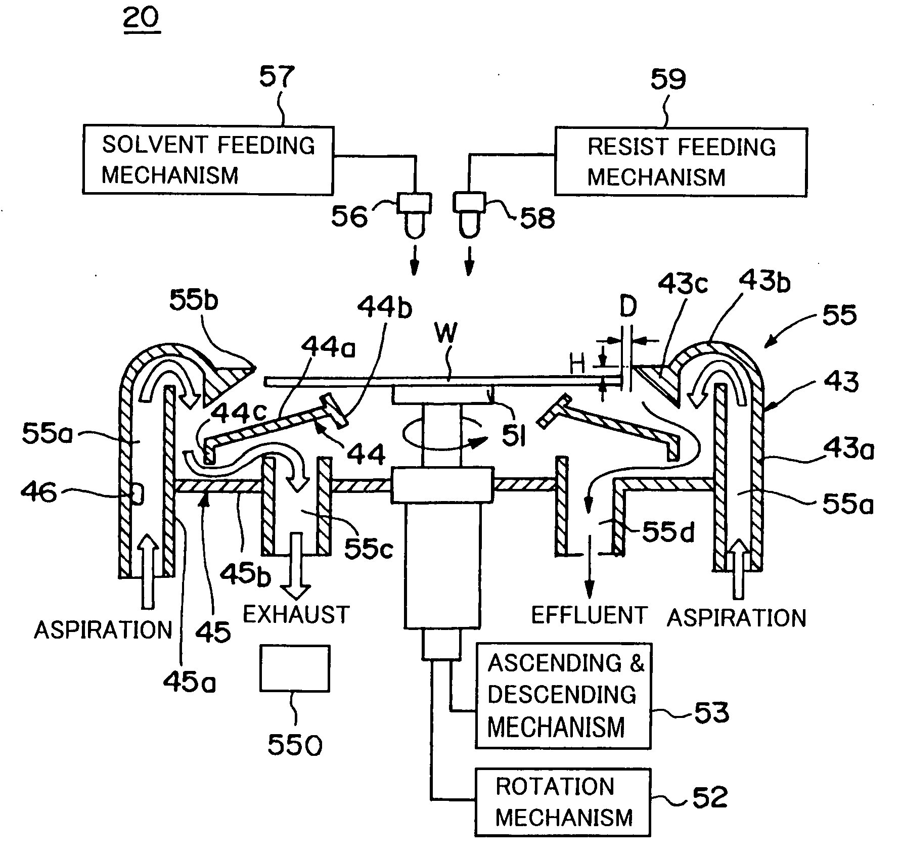
[0083] Thus the present invention in the first embodiment allows opening 55b and the perimeter of wafer W to have only a small distance therebetween and separates a processing space located above wafer W in which resist is applied on wafer W and a space located below wafer W for exhaust and effluent. Thus the applied liquid that is spun away from the perimeter of the substrate can be recovered in the processing cup and the mist formed in processing cup 55 that leaks above wafer W can be reduced or prevented.

[0084] Furthermore, aspiration port 55a for aspirating external air into processing cup 55, and exhaust port 55c for exhausting outside processing cup 55 are provided. An exhaust flow path can thus be formed in processing cup 55, and a mist produced in forming the film to be applied can be exhausted even with small aspiration.

[0085] Furthermore, as an exhaust flow path is formed, as described above, there is not external air intensely flowing in from opening 55 as air is exhaust...

second embodiment

[0104] Thus the present invention in the second embodiment allows resist liquid to be dispersed on a surface of wafer W in a sealed processing space with a processing atmosphere fed with a solvent (a thinner) for the resist liquid in the form of a mist to suppress evaporation of the solvent dispersed and thus prevent a substrate from having a perimeter with the dispersed resist liquid dried and thus solidified thereon.

[0105] Thus in addition to the effect obtained in the first embodiment the resist liquid can form a film more uniform in thickness, and the resist liquid can also be reduced in amount for use and exhaust and effluent can also be reduced in amount.

[0106] Note that, as has been described in the first and second embodiments, aspiration port 55a is provided with flowmeter 46. If an aspiration device performing aspiration through exhaust port 55c is not driven and thus stops, however, there is a possibility that processing cup 55 may have the mist remaining therein and thu...


PUM


Abstract

There is provided an apparatus including: a processing cup having an opening opened upward to allow a substrate to be loaded and unloaded, an exhaust port for exhausting an unnecessary atmosphere produced in forming a film applied on the substrate, and an aspiration port for aspirating external air; and an aspiration device aspirating the unnecessary atmosphere through the exhaust port, wherein when the substrate is accommodated in the opening of the processing cup, the substrate has a perimeter spaced from the opening by a predetermined gap, and below the substrate accommodated in the processing cup there is formed an exhaust flow path extending from the aspiration port to the exhaust port.

Description

BACKGROUND OF THE INVENTION [0001] 1. Field of the Invention [0002] The present invention relates generally to apparatuses and methods of forming a film of liquid applied on a substrate and particularly to apparatuses dropping a liquid to be applied on an upper surface of a substrate held substantially horizontally and rotated as controlled to disperse the liquid in the form of a film to form a film to be applied and methods of forming such film. [0003] 2. Description of the Background Art [0004] In fabricating a semiconductor device a photolithography process is performed including, e.g., the step of applying resist liquid serving as a liquid to be applied on a semiconductor wafer (hereinafter simply referred to as a “wafer”) serving as a substrate to be processed to form a film of the resist, the step of exposing the film of the resist to form the film of the resist in a predetermined pattern, the step of heating the exposed film of the resist to promote a chemical reaction therei...

Claims


Application Information

Patent Timeline
Patent Type & Authority Applications(United States)
IPC IPC(8): B05D3/12B05C11/02B05B15/04B05C11/00
CPCG03F7/162H01L21/6715H01L21/67051G03F7/70933
Inventor YOSHIHARA, KOUSUKEINADA, HIROICHI
Owner TOKYO ELECTRON LTD
Why Eureka
Try Eureka