Fuel-cell apparatus

a fuel-cell apparatus and fuel cell technology, applied in the direction of cell components, electrochemical generators, machines/engines, etc., can solve the problems of low efficiency of the entire fuel-cell apparatus, achieve the effect of reducing the size of the compressed air supply device, reducing the power consumption of the compressor, and reducing the fatigue life of the bearing

Inactive Publication Date: 2007-03-29
JTEKT CORP
View PDF8 Cites 8 Cited by
  • Summary
  • Abstract
  • Description
  • Claims
  • Application Information

AI Technical Summary

Benefits of technology

[0012] With the aforementioned foil bearings, during the rotation of the rotation shaft, ambient air is drawn into the gaps between the bearing foils and the rotation shaft to generate pressures (dynamic pressures), thereby holding the rotation shaft in a non-contact manner. Accordingly, the rotation shaft is supported in both the radial and axial directions by the foil bearings, which can suppress the reduction of the fatigue life of the bearings due to high-speed rotation and also can eliminate the necessity of providing the function of circulating lubricating

Problems solved by technology

In fuel-cell apparatuses for use in fuel-cell vehicles, it has become a critical challenge to increase the efficiencies thereof, and there has also been a need for further increasing the efficiencies of the compressed-air supplying devices therein.
However, with the scroll compressor described in the aforementioned Patent Lite

Method used


Image

  • Fuel-cell apparatus
  • Fuel-cell apparatus
  • Fuel-cell apparatus

Examples


Embodiment Construction

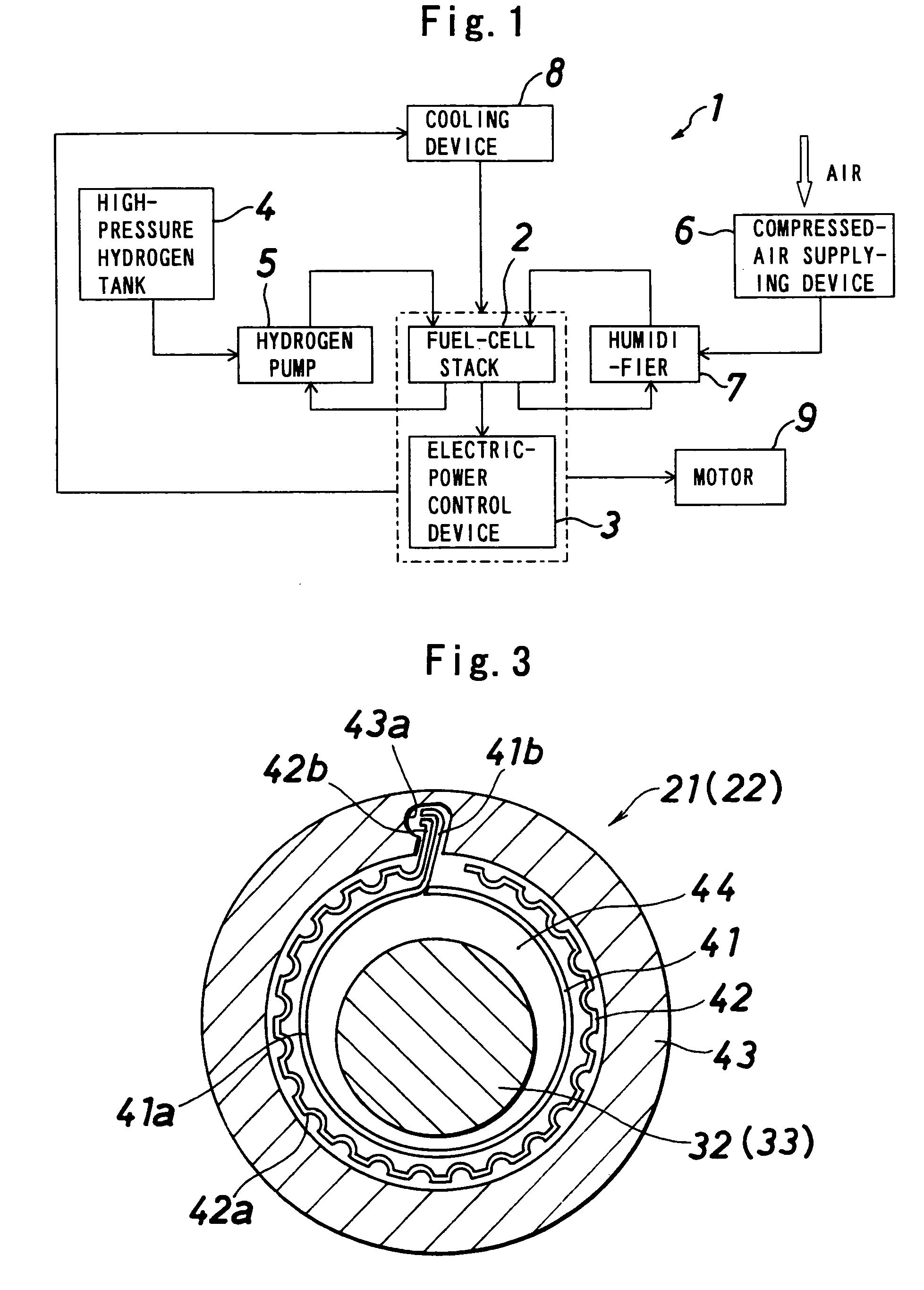
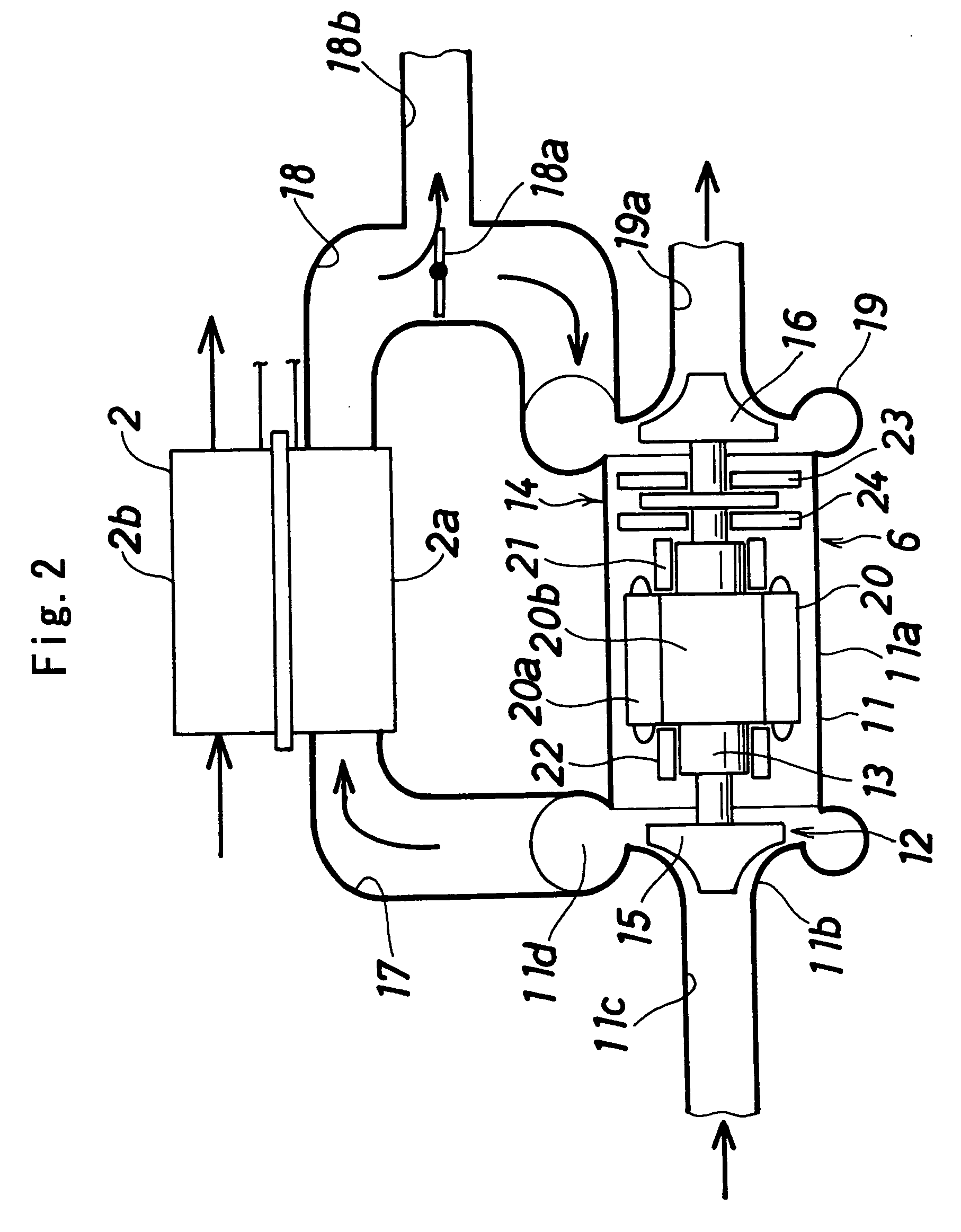
[0018] There will be described an embodiment of the present invention, with reference to the drawings. In the following description, the right and the left in FIG. 2 will be designated as front and back.

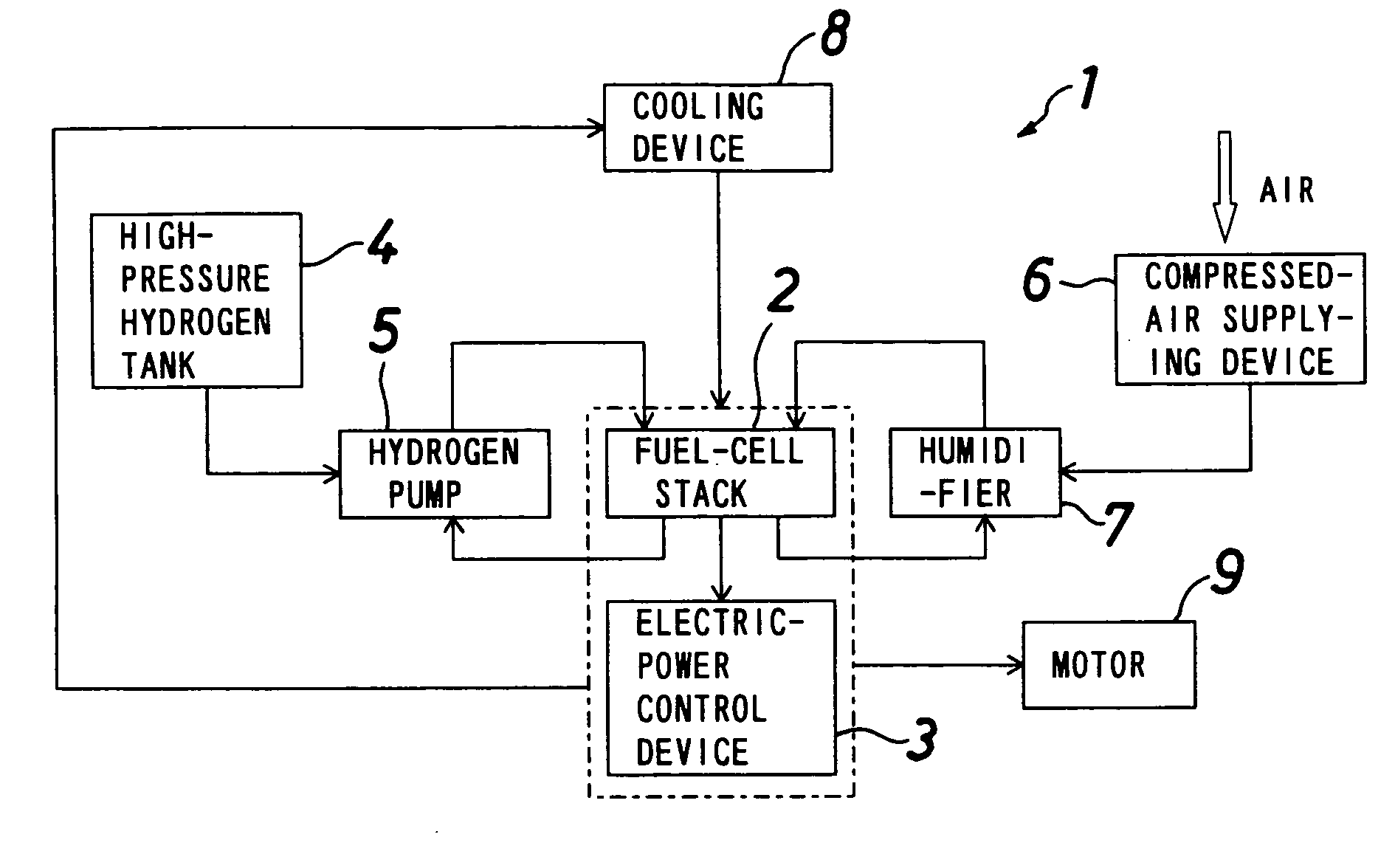
[0019]FIG. 1 is a block diagram of a fuel-cell apparatus according to the present invention which is mounted to a vehicle. The fuel-cell apparatus (1) includes a fuel-cell stack (2), an electric-power control device (3) which controls the electric power supplied from the fuel-cell stack (2), a high-pressure hydrogen tank (4) and a hydrogen pump (5) which supply hydrogen to the fuel-cell stack (2), a compressed-air supplying device (6) which supplies compressed air to the fuel-cell stack (2), a humidifier (7) which humidifies the compressed air supplied from the compressed-air supplying device (6), and a cooling device (8) which cools the fuel-cell stack (2) and the electric-power control device (3), wherein a motor (9) for running the vehicle is driven by the electric energy provide...


PUM


Abstract

A fuel-cell compressed-air supplying device 6 includes a compressor 12 including an impeller 15 provided on one side of a rotation shaft 13 and a turbine 16 provided on the other side of the rotation shaft 13 of the compressor 12. Compressed air is supplied to a fuel-cell stack 2 through the rotation of the impeller 15, and exhaust air exhausted from the fuel-cell stack 2 causes the turbine 16 to rotate.

Description

BACKGROUND OF THE INVENTION [0001] The present invention relates to a fuel-cell apparatus for creating energy from hydrogen and oxygen, and, in particular, to a fuel-cell apparatus capable suitably mounted to a vehicle. [0002] Prototypes of fuel-cell vehicles which incorporate fuel-cells for running have been already fabricated, and Patent Literature 1 (JP-A No. 2002-70762) suggests a fuel-cell vehicle incorporating a scroll compressor as a device suitable for supplying compressed air to the fuel-cells in the fuel-cell vehicle. [0003] In fuel-cell apparatuses for use in fuel-cell vehicles, it has become a critical challenge to increase the efficiencies thereof, and there has also been a need for further increasing the efficiencies of the compressed-air supplying devices therein. [0004] However, with the scroll compressor described in the aforementioned Patent Literature 1, the electricity generated from the fuel-cells is partially utilized for driving the compressed-air supplying de...

Claims


Application Information

Patent Timeline
IPC IPC(8): H01M8/04
CPCF01D15/10F02C1/05F02C6/12Y02E60/50F16C17/024H01M8/04111F02C7/06
Inventor TANIGUCHI, MANABUMIYAGAWA, YASUKATAUEYAMA, HIROCHIKA
Owner JTEKT CORP
Why Eureka
Try Eureka