

Method and apparatus for manufacturing a display apparatus
a technology of display apparatus and manufacturing method, which is applied in the direction of electrical apparatus, cathode ray tube/electron beam tube, electric discharge tube, etc., can solve the problems of inability to divide the front substrate and the back substrate so large, the interval between the dividing lines is extremely narrow, and the electron-emitting elements of the cathode unit and the fluorescent screen of the anode unit may be broken or damaged, etc. problems, to achieve the effect of dividing
- Summary
- Abstract
- Description
- Claims
- Application Information
AI Technical Summary
Benefits of technology
Problems solved by technology
Method used
Image

Examples
first embodiment
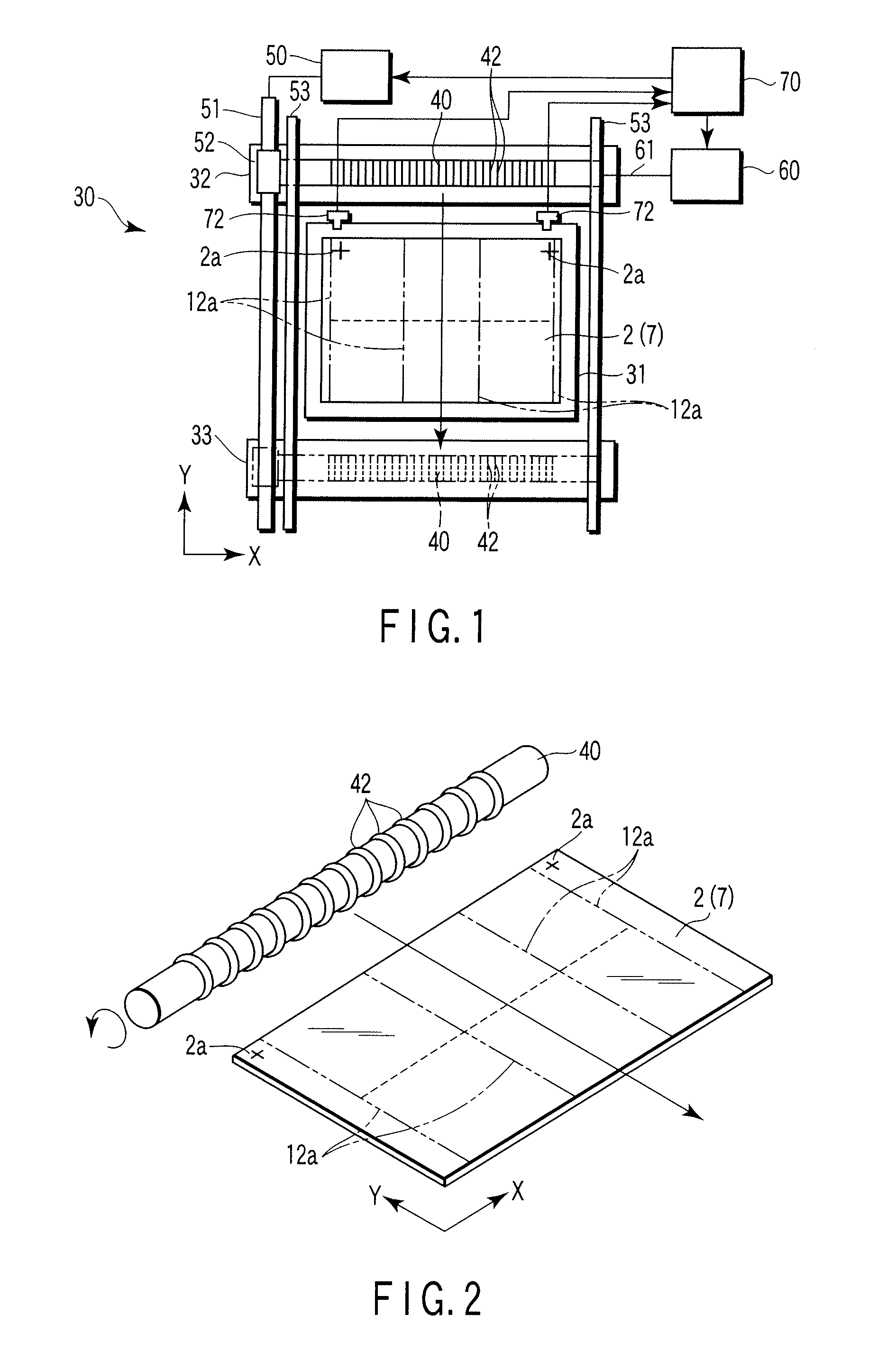
[0038] A first embodiment of the present invention will be described, with reference to FIG. 1 and FIG. 2. FIG. 1 shows a thin-film cutting apparatus 30, which is an apparatus for manufacturing a display apparatus, according to the present invention. As shown in FIG. 1, the apparatus 30 comprises an XYZθ table 31, a waiting unit 32, a washing-drying unit 33, a roller cutter 40, a roller-driving unit 50, a roller-rotating unit 60, a controller 70, and position sensors 72.
[0039] The XYZθ table 31 plays a role of a table for holding a front substrate 2 that is to be processed. The table 31 has a rectangular upper surface that is slightly larger than the substrate 2. The table 31 has a plurality of vacuum suction holes. The holes open at the upper surface and are used to hold, by suction, the substrate 2 on the upper surface of the table 31. The substrate 2 is held on the XYZθ table 31, with its long side extending in X direction and its short side extending in Y direction. The positio...
second embodiment
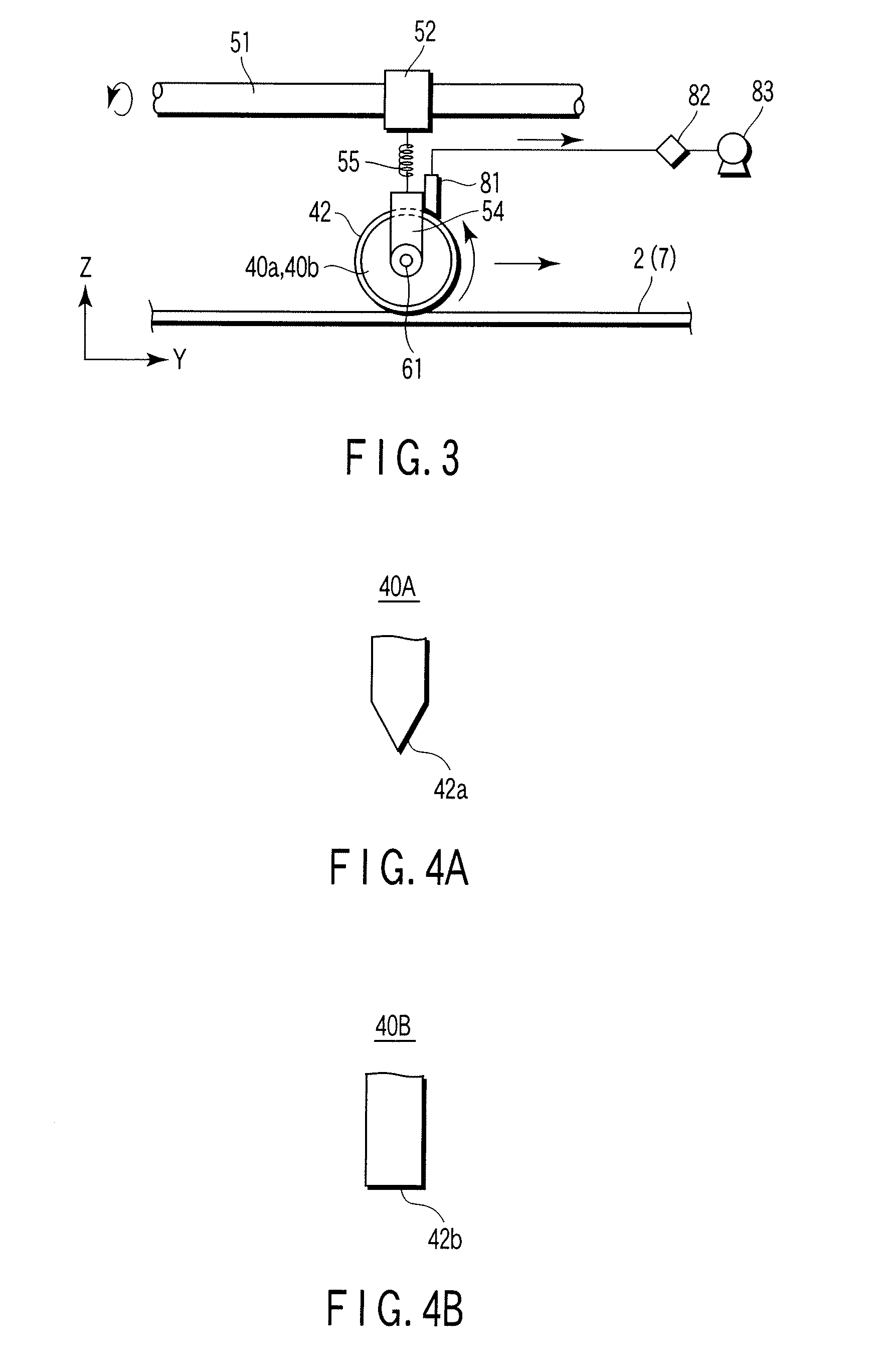
[0052] A second embodiment of the present invention will be described with reference to FIG. 3.
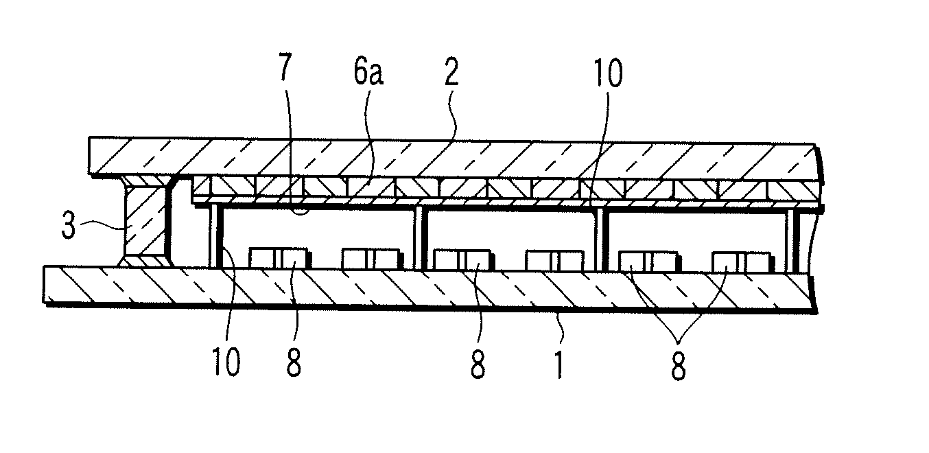
[0053] The roller cutter of the second embodiment comprises two roller cutters 40a and 40b that are divided and has the same length. The rollers 40a and 40b are supported by holders 54 and can rotate around shafts 61. Each holder 54 is coupled to a ball nut 52 by a compression spring 55 and a connecting rod (not shown). The compression spring 55 is a follower means for helping the cutter blade 42 of the roller cutter to move flexibly in the Z direction. Hence, the roller cutters 40a and 40b divide an Al metal back layer 7, slightly moving up and down as they move in contact with minute depressions and projections of the Al metal back layer 7. Since the compression springs 55 pushes the cutter blades 42 onto the Al metal back layer, applying a predetermined pressure (low pressure) to the meta back layer, the blade 42 do not bite into the substrate located beneath the metal back layer. This...
third embodiment
[0056] A third embodiment of the present invention will be described, with reference to FIG. 4A to FIG. 4D.
[0057] The embodiment can use such various types of roller cutters 40a, 40b and 40c as shown in FIG. 4A to FIG. 4D. The roller cutter 40a shown in FIG. 4A has a cutter blade 42a that has a projecting edge. The cutter blade 42a can cut slits having a minimum width of a few microns, in an Al metal back layer. The roller cutter 40b shown in FIG. 4B has a cutter blade 42b that has a flat edge. The cutter blade 42b can cut slits having a prescribed width, in an Al metal back layer.
[0058] The roller cutter 40c shown in FIG. 4C has a cutter blade 42c that has a depressed edge. The cutter blade 42c makes it easy to transport Al chips made during the cutting process, to a vacuum cleaner 81. The roller cutter 40d shown in FIG. 4D has a cutter blade 42c that has a depressed edge, like the blade described above. The cutter blade 42c has a suction groove 42 that communicates with a vacuum...
PUM
 Abstract
Description
Claims
Application Information