Waste energy recovery method and waste energy recovery system

a waste heat energy recovery and waste heat energy technology, applied in the direction of machines/engines, mechanical equipment, sustainable manufacturing/processing, etc., can solve the problems of reducing the viscosity of waste heat, poor energy use efficiency, damage to hydraulic equipment, etc., to recover waste heat energy, improve the energy use efficiency of the engine, and recover waste heat energy

Inactive Publication Date: 2007-04-05
SHIN CATERPILLAR MITSUBISHI LTD CORP
View PDF5 Cites 25 Cited by
  • Summary
  • Abstract
  • Description
  • Claims
  • Application Information

AI Technical Summary

Benefits of technology

[0025] According to another feature of the present invention by transferring waste heat energy to the low-boiling medium from the hydraulic oil that has increased in temperature as a result of loss of energy in the hydraulic circuit as well as the other fluid that has increased in temperature as a result of operation of the engine, the hydraulic oil and the other fluid are cooled while the low-boiling medium is vaporized. And by providing the turbine with the vaporized low-boiling medium through the low-boiling medium circuit in order to drive the turbine so that the turbine provides a boost to the engine and thereby recovers the waste heat energy. As a part of the lost engine power, which would, in case of a conventional art, wastefully dissipate into the air as waste heat energy from the oil cooler and the other cooling means, can be effectively recirculated to the engine by means of the low-boiling medium circuit and the turbine, the energy use efficiency of the engine can be improved.
[0026] According to yet another feature of the present invention by transferring waste heat energy from the hydraulic oil and engine cooling water to the low-boiling medium, the hydraulic oil and the engine cooling water are cooled while the low-boiling medium is vaporized. And by providing the turbine with the vaporized low-boiling medium through the low-boiling medium circuit in order to drive the turbine so that the turbine provides a boost to the engine and thereby recovers the waste heat energy. As a part of the lost engine power, which would, in case of a conventional art, wastefully dissipate into the air as waste heat energy from the oil cooler and the radiator, can be effectively recirculated to the engine by means of the low-boiling medium circuit and the turbine, the energy use efficiency of the engine can be improved.
[0027] According to yet another feature of the present invention by transferring waste heat energy to the low-boiling medium from the hydraulic oil that has increased in temperature as a result of loss of energy in the hydraulic circuit as well as the engine intake air that has increased in temperature as a result of being compressed by the turbocharger, the hydraulic oil and the engine intake air are cooled while the low-boiling medium is vaporized. And by providing the turbine with the vaporized low-boiling medium through the low-boiling medium circuit in order to drive the turbine so that the turbine provides a boost to the engine and thereby recovers the waste heat energy. As a part of the lost engine power, which would, in case of a conventional art, wastefully dissipate into the air as waste heat energy from the oil cooler and the intake air cooler, can be effectively recirculated to the engine by means of the low-boiling medium circuit and the turbine, the energy use efficiency of the engine can be improved.
[0028] According to yet another feature of the present invention by transferring waste heat energy to the low-boiling medium from the hydraulic oil that has increased in temperature as a result of loss of energy in the hydraulic circuit,

Problems solved by technology

An oil cooler is provided to reduce the temperature of the hydraulic oil, because a rise in the temperature of the hydraulic oil causes thermal degradation of the oil as well as a de

Method used


Image

  • Waste energy recovery method and waste energy recovery system
  • Waste energy recovery method and waste energy recovery system
  • Waste energy recovery method and waste energy recovery system

Examples


Embodiment Construction

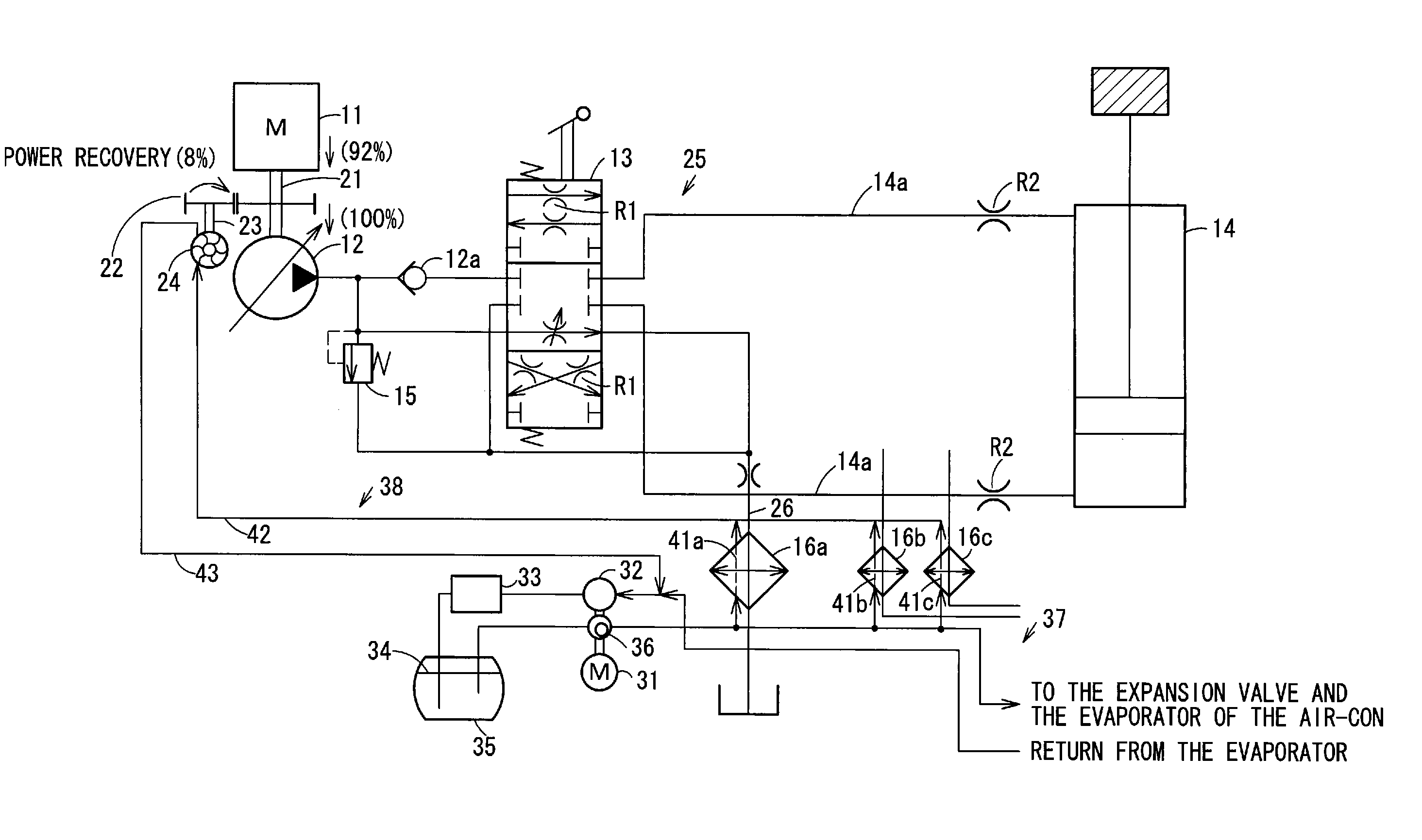
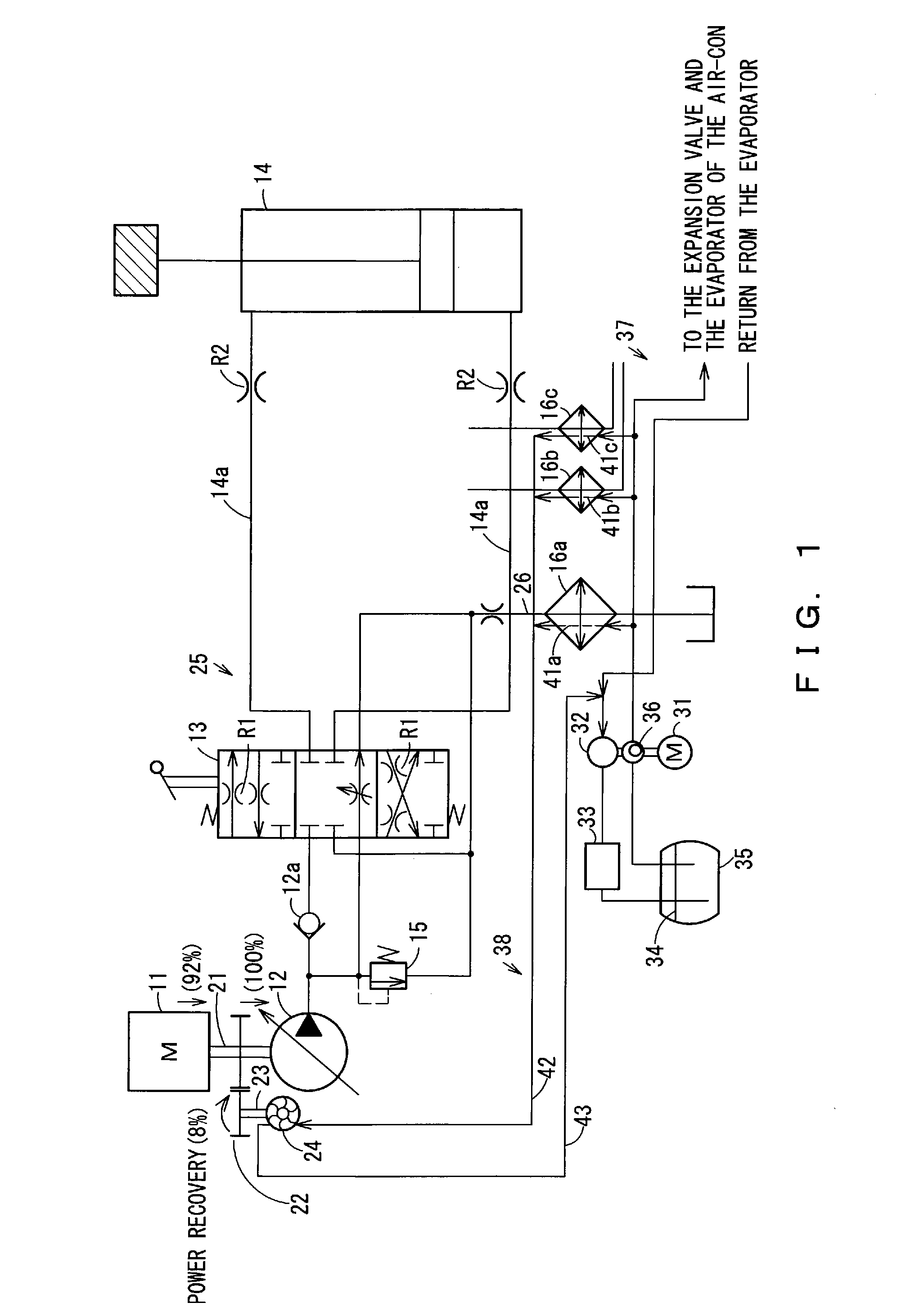
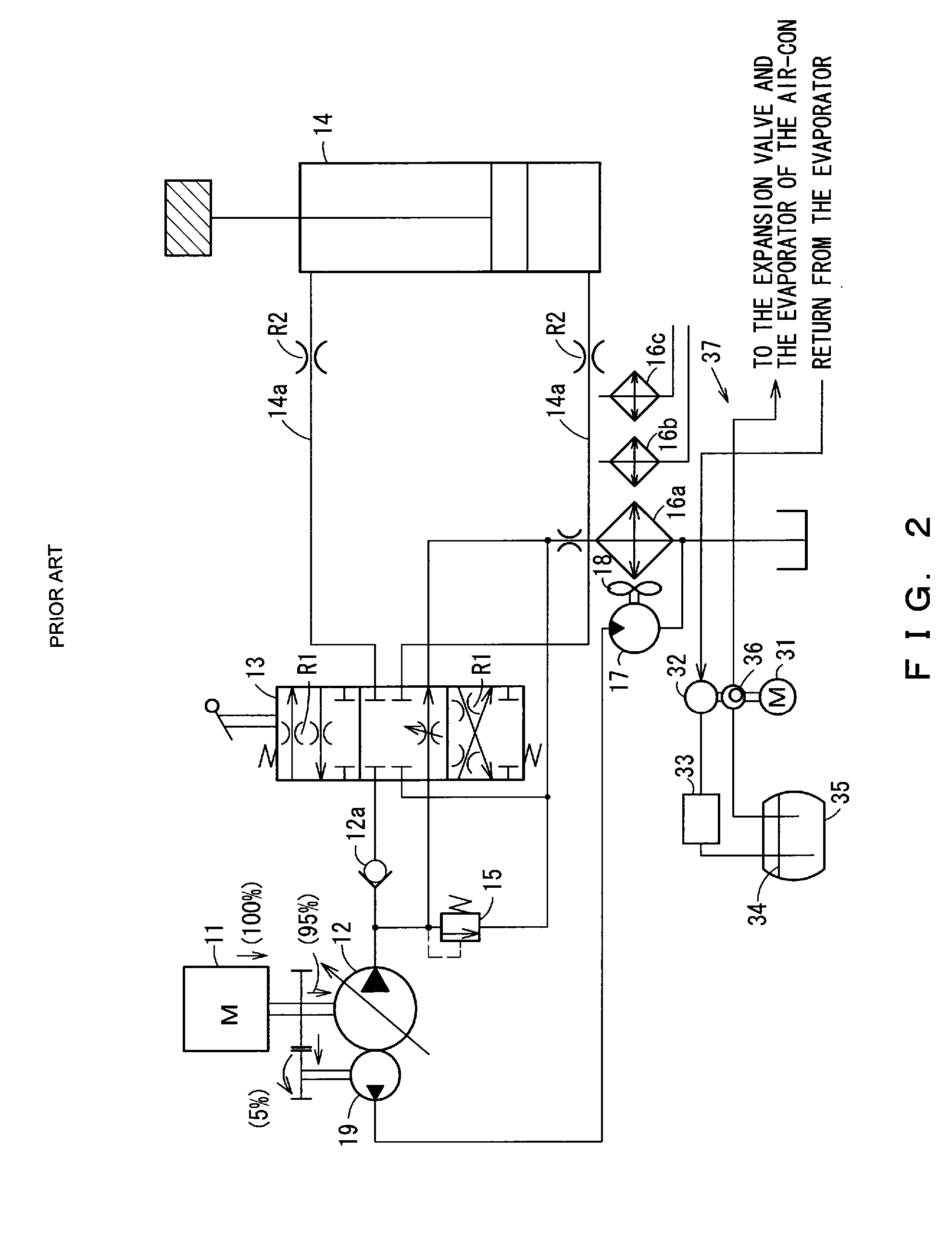
[0033] The present invention is explained hereunder, referring to FIG. 1. The elements similar to those of the conventional art shown in FIG. 2 are identified with the same reference codes, and their explanation is omitted hereunder.

[0034] As shown in FIG. 1, a diesel engine (hereinafter simply referred to as engine) 11 is mounted on a construction machine, such as a hydraulic excavator. The engine 11 is adapted to drive a pump, i.e. main pump 12, through a driving shaft unit 21 and an engine gear unit 22 that branches off from the driving shaft unit 21. The driving shaft unit 21 serves as a power transmission unit, and the engine gear unit 22 serves as a power transmission system. In place of a conventional hydraulic cooling pump 19, a steam turbine (hereinafter simply referred to as turbine) 24 is provided for the engine 11. The turbine 24 is a small power recovery turbine adapted to be rotated by means of energy provided by vaporized low-boiling medium (what is widely known as r...


PUM


Abstract

An oil cooler for cooling hydraulic oil that has increased in temperature due to energy loss in a hydraulic circuit a radiator for cooling engine cooling water that has increased in temperature as a result of cooling an engine and an ATAAC for cooling engine intake air that has increased in temperature as a result of being compressed by a turbocharger, are provided with heat pipes for vaporizing low-boiling medium by absorbing heat from the oil cooler the radiator and the ATAAC. A power recovery turbine is rotated by energy provided by vaporized low-boiling medium is provided for the engine. A low-boiling medium circuit is provided so as to drive the turbine by feeding the low-boiling medium that has been vaporized by waste heat energy. The low-boiling medium circuit includes the heat pipes of the oil cooler the radiator, and the ATAAC, as well as the turbine.

Description

CROSS-REFERENCE TO PRIOR APPLICATION [0001] This is a U.S. National Phase Application under 35 U.S.C. §371 of International Patent Application No. PCT / JP2005 / 006628, filed Apr. 5, 2005, and claims the benefit of Japanese Patent Application No. 2004-273991, filed Sep. 21, 2004, both of which are incorporated by reference herein. The International Application has not published yet at the time of filing of this application.TECHNICAL FIELD [0002] 1. Field of the Invention [0003] The present invention relates to a waste heat energy recovery method and a waste heat energy recovery system for recovering waste heat energy generated from a hydraulic circuit or any other similar system. [0004] 2. Background Art [0005] A conventional construction machine typically has such a configuration that power is supplied from an engine, which is normally a diesel engine, to a main pump so that pressurized oil is fed from the main pump to actuator control valves. [0006] An actuator that has been supplied...

Claims


Application Information

Patent Timeline
IPC IPC(8): F01K23/06F15B21/0423
CPCE02F9/2217F01K15/02F01K23/02F01K25/00F01P2003/2278F01P2060/02F01P2060/04F02B29/0443F15B21/042F15B21/14F15B2211/88Y02T10/16Y02P80/15Y02T10/12F15B21/0423
Inventor YOSHINO, KAZUNORI
Owner SHIN CATERPILLAR MITSUBISHI LTD CORP
Why Eureka
Try Eureka