Electromechanical Latching Relay and Method of Operating Same

a latching relay and electromechanical technology, applied in the field of latching electromechanical relays, can solve the problems of large coil size, high unit-to-unit variability and high unit cost, and the “assembly-line” type process generally has relatively complicated structures, etc., and is impossible or very difficult to fabricate other than using conventional winding methods

Inactive Publication Date: 2007-04-05
SHEN JUN +1
View PDF42 Cites 23 Cited by
  • Summary
  • Abstract
  • Description
  • Claims
  • Application Information

AI Technical Summary

Benefits of technology

[0014] The above problems and others are at least partially solved and the above purposes and others are realized in a relay including a first magnet mounted on a movable cantilever and a second magnet placed near the first magnet. The first magnet is permanently magnetized along its long (horizontal) axis. The cantilever has a first end associated to the first pole (e.g., north pole) of the first magnet, and a second end associated to the second pole (e.g., south pole) of the first magnet. When the first end of the cantilever approaches the second magnet, the first pole of the first magnet induces a local opposite pole (e.g., south pole) in the second magnet and causes the first end of the cantilever to be attracted to the local opposite pole of the second magn

Problems solved by technology

The individual relays produced by such an “assembly-line” type process generally have relatively complicated structures and exhibit high unit-to-unit variability and high unit cost.
One drawback of these traditional latching relay designs is that they require the coil to generate a relatively large reversing magnetic field in order to transfer the armature from one position to the other.
This requirement mandates a large number of wir

Method used


Image

  • Electromechanical Latching Relay and Method of Operating Same
  • Electromechanical Latching Relay and Method of Operating Same
  • Electromechanical Latching Relay and Method of Operating Same

Examples


example 1

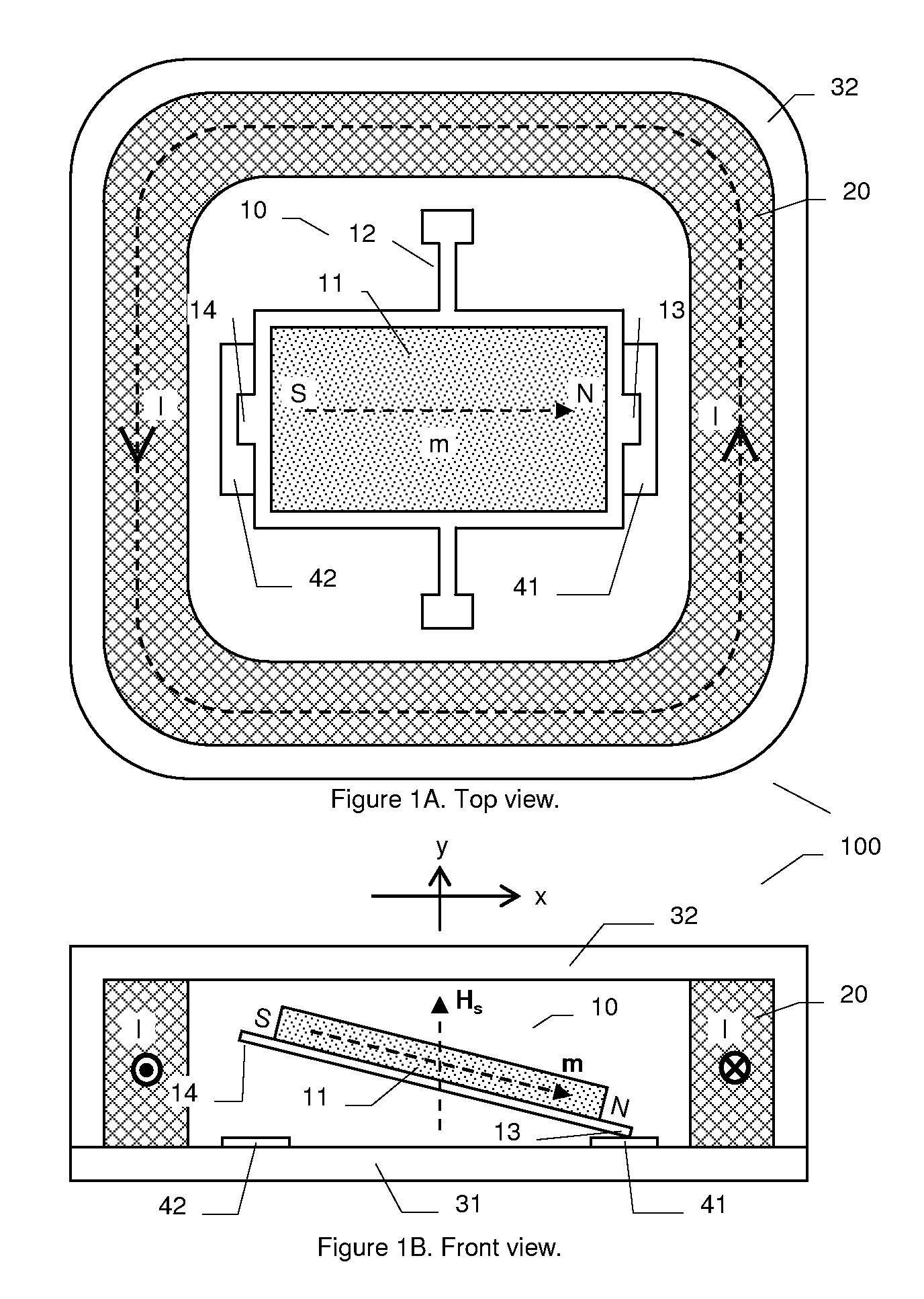
[0031] Assuming the first magnet having the following characteristics: length=4 mm (along long axis), width=4 mm, thickness=0.2 mm, volume V=length×width×thickness, remnant magnetization Br=μ0M=1 T, the magnetic moment μ0m=μ0M×V=3.2×10⁻⁹ T·m3. For a coil-induced magnetic field μ0Hs=0.05 T (Hs=500 Oe), the induced magnetic torque about the length center is Ts=μ0m×Hs=1.27×10⁻⁴ m·N (assuming m is perpendicular to Hs) which corresponds to a force of Fm=Ts / (length / 2)=6.4×10⁻² N at the end of the first magnet. This force, combining with the flexure restoring force, needs to be larger than the pole attraction for cantilever switching. The above exemplary parameters show that for a relatively small coil-induced magnetic field (Hs=500 Oe), a significantly large torque and force can be generated. The torque and force can continue to increase with larger Hs (correspondingly larger coil current). Another point worth noting is that when the angle between m and Hs changes from perfectly perpendic...

example 2

[0032] Assuming all the dimensions of the first magnet are reduced by an order of magnitude: length=0.4 mm (along long axis), width=0.4 mm, thickness=0.02 mm, remnant magnetization Br=μ0M=1 T, the magnetic moment μ0m=μ0M×V=3.2×10⁻¹² T·m3. For a coil-induced magnetic field μ0Hs=0.05 T (Hs=500 Oe), the induced magnetic torque about the length center is Ts=μ0m×Hs=1.27×10⁻⁷ m·N (assuming m is perpendicular to Hs) which corresponds to a force of Fm=Ts / (length / 2)=6.4×10⁻⁴ N at the end of the first magnet. The force is still quite large in such micro dimensions.

Fabricating a Latching Relay

[0033] It is understood that a variety of methods can be used to fabricate the latching relay. These methods include, but not limited to, semiconductor integrated circuit fabrication methods, printed circuit board fabrication methods, micro-machining methods, and so on. The methods include processes such as photo lithography for pattern definition, deposition, plating, screen printing, etching, laminat...


PUM


Abstract

A latching relay employing a movable cantilever with a first permanent magnet and a nearby second magnet is disclosed. The permanent magnet affixed to the cantilever is permanently magnetized along its long (horizontal) axis. The cantilever has a first end associated to the first pole (e.g., north pole) of the first magnet, and a second end associated to the second pole (e.g., south pole) of the first magnet. When the first end of the cantilever approaches the second magnet, the first pole of the first magnet induces a local opposite pole (e.g., south pole) in the second magnet and causes the first end of the cantilever to be attracted to the local opposite pole of the second magnet, closing an electrical conduction path (closed state). An open state on the first end of cantilever 10 can be maintained either by the second pole of first magnet being attracted to a local opposite pole in the second magnet or by a mechanical restoring force of flexure spring which supports the cantilever. A third electromagnet (e.g., a coil or solenoid), when energized, provides a third perpendicular magnetic field about the first magnet and produces a torque on the associated cantilever to force the cantilever to switch between closed and open states. A few alternate embodiments of the relay are also disclosed which include a case where the latching feature is disabled, and another case where an external magnet is used to switch the cantilever.

Description

CROSS REFERENCE TO RELATED APPLICATIONS [0001] This patent application claims the benefit of U.S. Provisional Patent Application Ser. No. 60 / 725,335, filed on Oct. 2, 2005, which is hereby incorporated by reference.FIELD OF THE INVENTION [0002] The present invention relates to relays. More specifically, the present invention relates to latching electromechanical relays and to methods of operating and formulating electromechanical relays. BACKGROUND OF THE INVENTION [0003] Relays are electromechanical switches operated by a flow of electricity in one circuit and controlling the flow of electricity in another circuit. A typical relay comprises basically an electromagnet with a soft iron bar, called an armature, held close to it. A movable contact is connected to the armature in such a way that the contact is held in its normal position by a spring. When the electromagnet is energized, it exerts a force on the armature that overcomes the pull of the spring and moves the contact so as t...

Claims


Application Information

Patent Timeline
IPC IPC(8): H01H51/22
CPCH01H1/0036H01H50/005H01H2001/0042H01H2036/0093H01H2050/007
Inventor SHEN, JUNWEI, CHENGPING
Owner SHEN JUN
Why Eureka
Try Eureka