Short range lidar apparatus having a flat spatial response

a spatial response and lidar technology, applied in the field of optical measuring devices, can solve the problems of limited temporal resolution, unoptimized, and the 1/rsup>2 /sup>dependence of the signal, and achieve the effect of flattening the spatial response of the apparatus

Inactive Publication Date: 2007-04-05
INSTITUT NATIONAL D'OPTIQUE
View PDF13 Cites 30 Cited by
  • Summary
  • Abstract
  • Description
  • Claims
  • Application Information

AI Technical Summary

Benefits of technology

[0020] The apparatus further includes a light-collecting arrangement having a field of view intersecting the optical path along the short range. The light-collecting arrangement includes light-receiving optics, receiving the back-scattered light, and a detector detecting the received back-scattered light. The light-collecting arrangement further includes a spatial filter spatially filtering the back-scattered light so as to flatten the spatial response of the apparatus.

Problems solved by technology

The major impairment of using standard LIDARs for short range applications is the 1 / r2 dependence of the signal, r being the distance from the target to the receiving optics.
Moreover, for lower cost operation, the temporal resolution is limited, usually between 10 and 20 nanoseconds, so that a data point represents the average density of aerosols in some volume covering 1.5 to 3 m along the path of the emitted beam.
This is not optimal.
These LIDARs are bulky, power hungry and very costly.
This patent however does not tackle the problem of large signal variation with distance for short ranges, nor does it discuss it.

Method used


Image

  • Short range lidar apparatus having a flat spatial response
  • Short range lidar apparatus having a flat spatial response
  • Short range lidar apparatus having a flat spatial response

Examples


Embodiment Construction

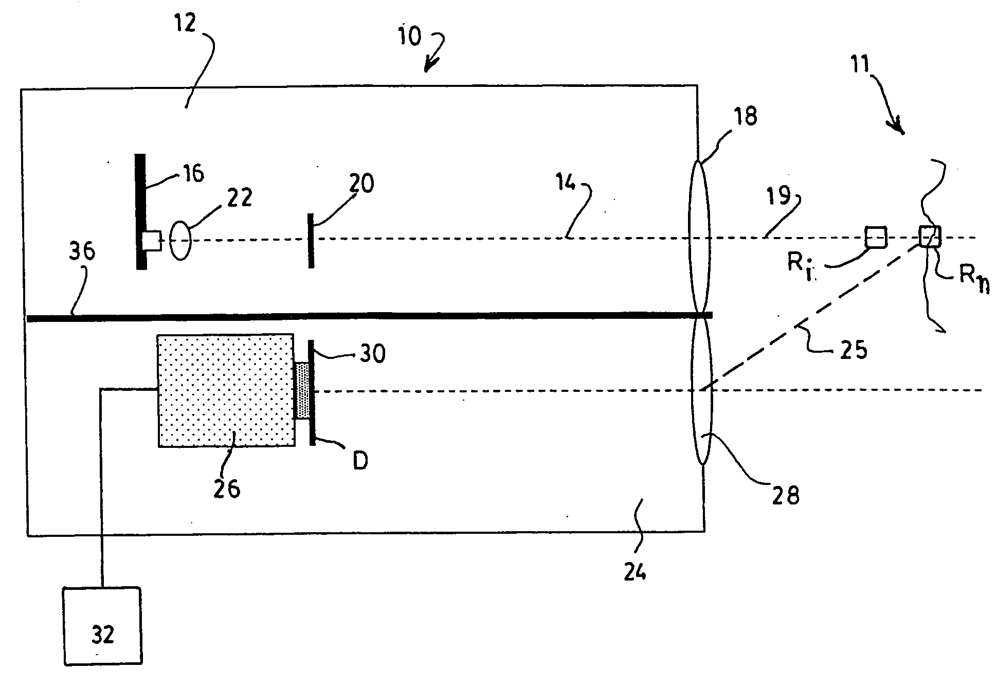
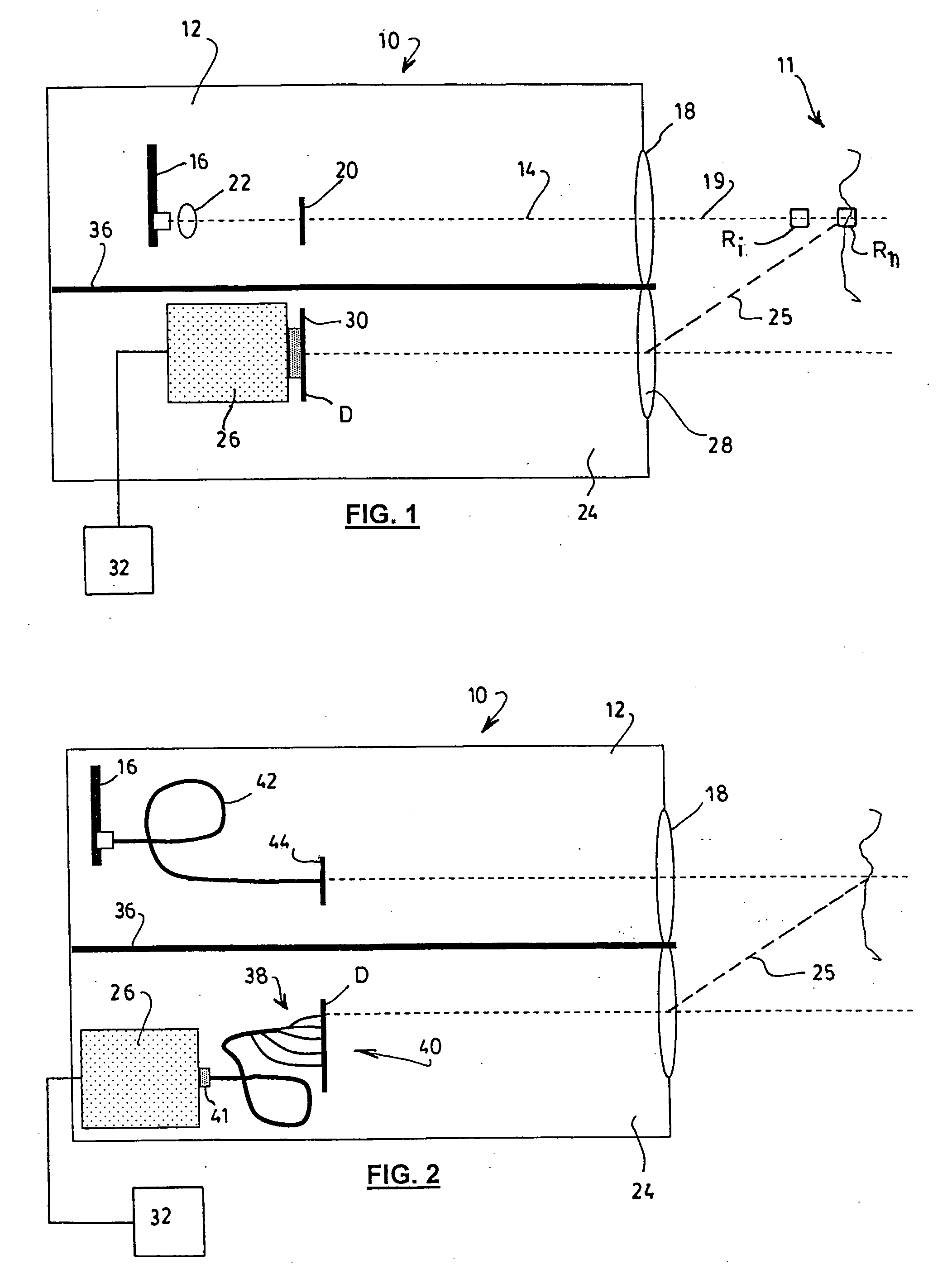
[0028] Referring to FIG. 1, there is schematically illustrated a LIDAR apparatus 10 having an almost flat spatial response according to a preferred embodiment of the present invention.

[0029] The apparatus is intended for measuring, at short range, concentrations of particles 11 in the air such as aerosols, fog, dust, clouds of chemical droplets such as pesticides, insecticides or the like, or suspensions in a liquid medium, for example in the course of analyzing the turbidity of water in waste water settling tanks.

[0030] The term “range” is used herein as referring to the distance between the detected particles 11 and the apparatus 10 itself. It is understood that the designation of “short range” for the apparatus 10 of the invention is by comparison to traditional aerosol detecting LIDAR devices, which are designed to operate at a range of about 200 m or more; in the preferred embodiments, the apparatus 10 is designed to be operated within 100 m, preferably within 50 m. It will o...


PUM

PropertyMeasurementUnit
diametersaaaaaaaaaa
distancesaaaaaaaaaa
distanceaaaaaaaaaa

Abstract

A flat spatial response LIDAR apparatus for detecting particles within a short range is provided. The apparatus includes a light source projecting a light beam which is back-scattered by the particles to be detected. The back-scattered light is received, detected and analyzed. A spatial filter spatially filters the received back-scattered light in order to flatten the spatial response of the apparatus, so that a same concentration of particles at any distance within the short range will generate a signal of substantially the same intensity. This is for example accomplished by a properly profiled mask disposed in front of the detector, or a plurality of spatially distributed waveguides. As a result, the LIDAR apparatus can compensate for the 1/r2 dependence, or other dependences of the back-scattered light on the distance r.

Description

FIELD OF THE INVENTION [0001] The present invention relates to optical measuring devices and more particularly concerns a LIDAR apparatus with a flat spatial response used for measuring concentrations of particles at a short range. DESCRIPTION OF THE PRIOR ART [0002] Many industrial fields require the short range detection of particles such as aerosols, fog or clouds of chemical droplets such as pesticides, insecticides and the like. Some also require detection of suspensions, in liquids such as water. [0003] The best known current optical solution for spatially resolved aerosol detection is the use of a LIDAR (LIgth Detection And Ranging) system. In a LIDAR, a pulsed light signal is sent and is back-scattered by the particles. A temporal and amplitude analysis of the back-scattered light determines the particle concentrations along the path of the emitted beam of light. The scattering phenomena observed by such devices may be instantaneous or delayed according to fluorescent, lumin...

Claims


Application Information

Patent Timeline
Patent Type & Authority Applications(United States)
IPC IPC(8): G01N21/00
CPCG01N21/53G01N2021/1793G01N2021/4709G01S7/4816G01S17/95Y02A90/10
Inventor BABIN, FRANCOISLEVESQUE, MARC
Owner INSTITUT NATIONAL D'OPTIQUE
Why Eureka
Try Eureka