
Laser imaging apparatus with variable power, orbit time and beam diameter

a technology of orbit time and beam diameter, applied in the field of optical imaging apparatus, can solve the problems of tissue damage and destruction, light to be emitted from the entire surface, and heating of skin and tissue immediately under the skin, so as to reduce the orbit time, the diameter of the breast, and the scan time for the breast

Inactive Publication Date: 2007-04-05
IMAGING DIAGNOSTIC SYST
View PDF8 Cites 6 Cited by
  • Summary
  • Abstract
  • Description
  • Claims
  • Application Information

AI Technical Summary

Benefits of technology

[0026] It is an object of the present invention to provide a breast scanning apparatus and method that maintains the measured signal level at the detectors to an acceptable level while controlling the temperature rise of the surface of the breast being scanned by adjusting one of the laser power, beam spot diameter and orbit time of the laser beam depending on the breast diameter at a scan plane.
[0028] It is still another object of the present invention to provide a breast scanning apparatus and method that changes one of the laser power, beam spot diameter and orbit time of the laser beam during the scan as the breast diameter changes at the level of the laser beam (scan plane) in such a way that the temperature rise on the surface of the breast is controlled.
[0030] The present invention also provides a method for scanning a breast, comprising: a) positioning a patient in a prone position on a support having an opening with one of her breasts vertically pendent through the opening; b) scanning the breast with a laser CT scanner with a laser beam orbiting around the breast; d) detecting with a plurality of detectors positioned in an arc around the breast the light transmitted through the breast; e) determining the perimeter of the breast; and f) decreasing the orbit time as the diameter of the breast at scanning planes decreases, thereby reducing the scan time for the breast.

Problems solved by technology

Exacerbating the light detection problem is the fact that the scattering in the breast causes the light to be emitted from the entire surface of the breast, even though only a several millimeter area is being illuminated.
This energy will cause heating of the skin and tissue immediately under the skin.
And excessive heating will cause pain and ultimately will cause tissue damage and destruction.

Method used


Image

  • Laser imaging apparatus with variable power, orbit time and beam diameter
  • Laser imaging apparatus with variable power, orbit time and beam diameter
  • Laser imaging apparatus with variable power, orbit time and beam diameter

Examples


Embodiment Construction

[0038] The present invention addresses the issue of increasing the throughput of a laser scanning system by increasing the laser power and proportionally decreasing the rotation time of the scanner, while maintaining the measured signal quality. The present invention further discloses modifying the laser power and / or rotation time and / or laser beam spot size as the breast diameter changes during the scan. This is done while advantageously controlling the temperature rise on the surface of the breast during the scan to an acceptable level.

[0039] As the system scans the breast, starting typically at the chest wall and progressing towards the nipple, the breast diameter D in Equation 5 at the level of the laser beam and the detectors will generally get smaller. Breasts are not necessarily circular in cross-section, but an approximation as a circle is sufficient for estimating heating. A circumscribing circular diameter or a circle with the same area or perimeter length as the actual c...


PUM


Abstract

An apparatus for breast scanning comprises a patient support for a patient to rest in a prone position, the support having an opening with one of her breasts vertically pendent through the opening for scanning; and a laser CT scanner disposed below the support for generating data for reconstruction of images of the breast. The laser CT scanner includes a laser beam for impinging on the breast. The laser beam is orbitable around the breast. The laser CT scanner includes a plurality of detectors positioned in an arc around the breast to simultaneously detect light transmitted through the breast. The measured signal level at the detectors is maintained to an acceptable level while controlling the temperature rise on the breast surface during scanning.

Description

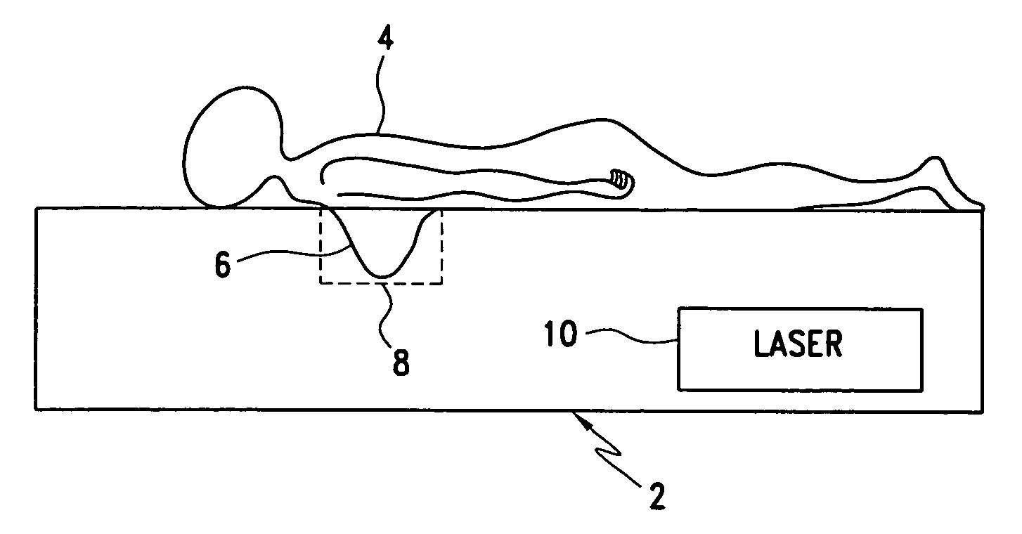
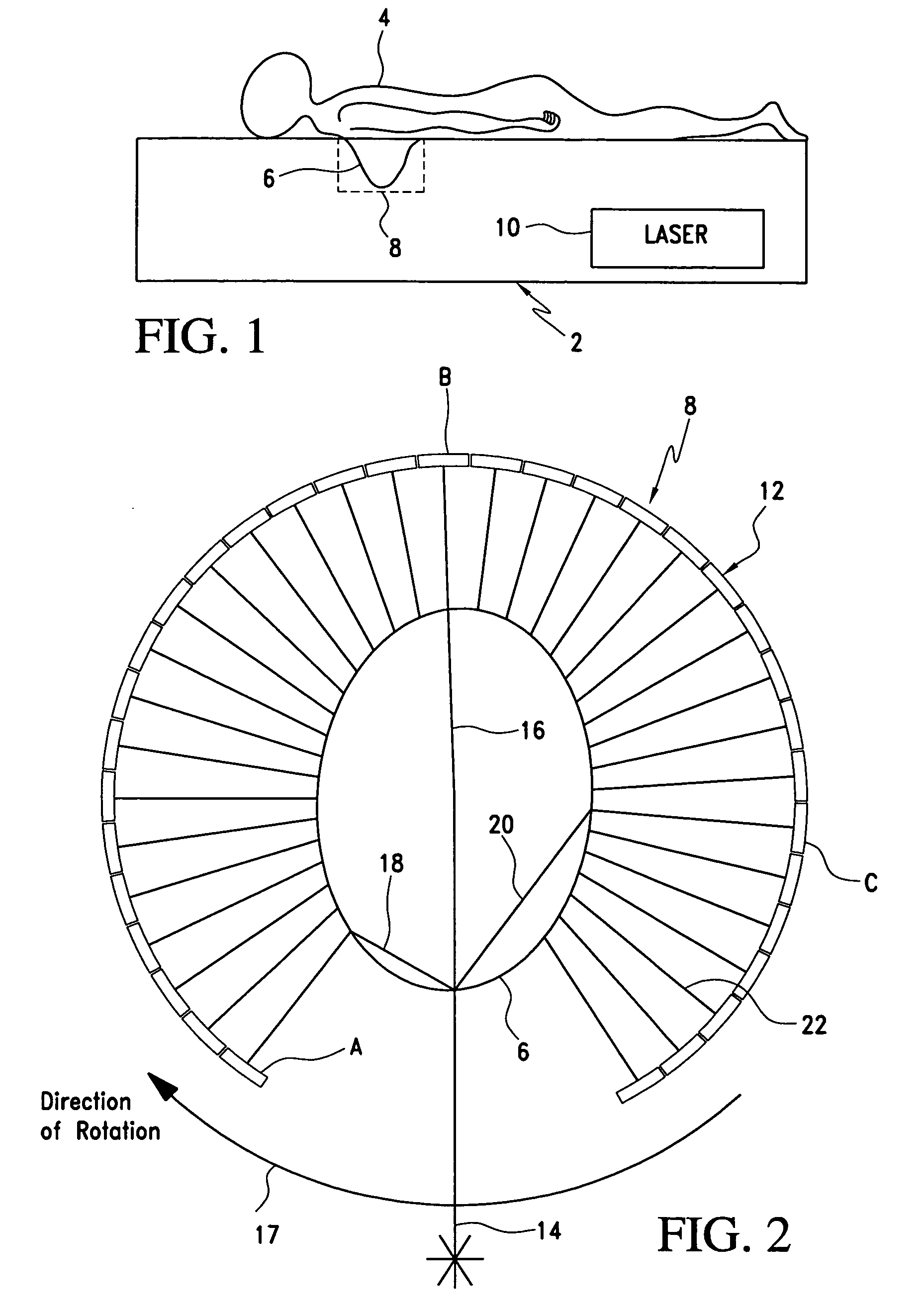
RELATED APPLICATION [0001] This is a nonprovisional application claiming the priority benefit of provisional application Ser. No. 60 / 723,004, filed Oct. 4, 2005, incorporated herein by reference.FIELD OF THE INVENTION [0002] The present invention is generally directed to optical imaging apparatus and in particular to laser CT scanners for imaging breasts. BACKGROUND OF THE INVENTION [0003] The attenuation of light through the breast in an optical tomographic scanner is very large, as high as 107:1. The typical optical CT scanner geometry, as described in U.S. Pat. No. 5,692,511, is illustrated in FIGS. 1 and 2, where a light source 10, typically a near-infrared laser, illuminates the scanned object, typically a breast 6. A ring of detectors 12 views the scanned object, each detector seeing light that is transmitted through a portion of the breast and re-emitted. For several detectors, the light paths 16, 18 and 20 are shown. [0004] The light levels at the detectors are generally qui...

Claims


Application Information

Patent Timeline
Patent Type & Authority Applications(United States)
IPC IPC(8): A61B5/05A61B6/00
CPCA61B5/0091A61B5/4312A61B5/0062
Inventor WAKE, ROBERTPONDER, STEVENBECKER, GARY
Owner IMAGING DIAGNOSTIC SYST
Learn More