

Working machine fuel management system and fuel managing method
a technology for managing systems and working machines, applied in the direction of electric control, instruments, anti-theft devices, etc., can solve the problems of not being able to supply information and being subject to damag
- Summary
- Abstract
- Description
- Claims
- Application Information
AI Technical Summary
Benefits of technology
Problems solved by technology
Method used
Image

Examples
Embodiment Construction
[0020] In the following, embodiments of the present invention will be explained based on the drawings.
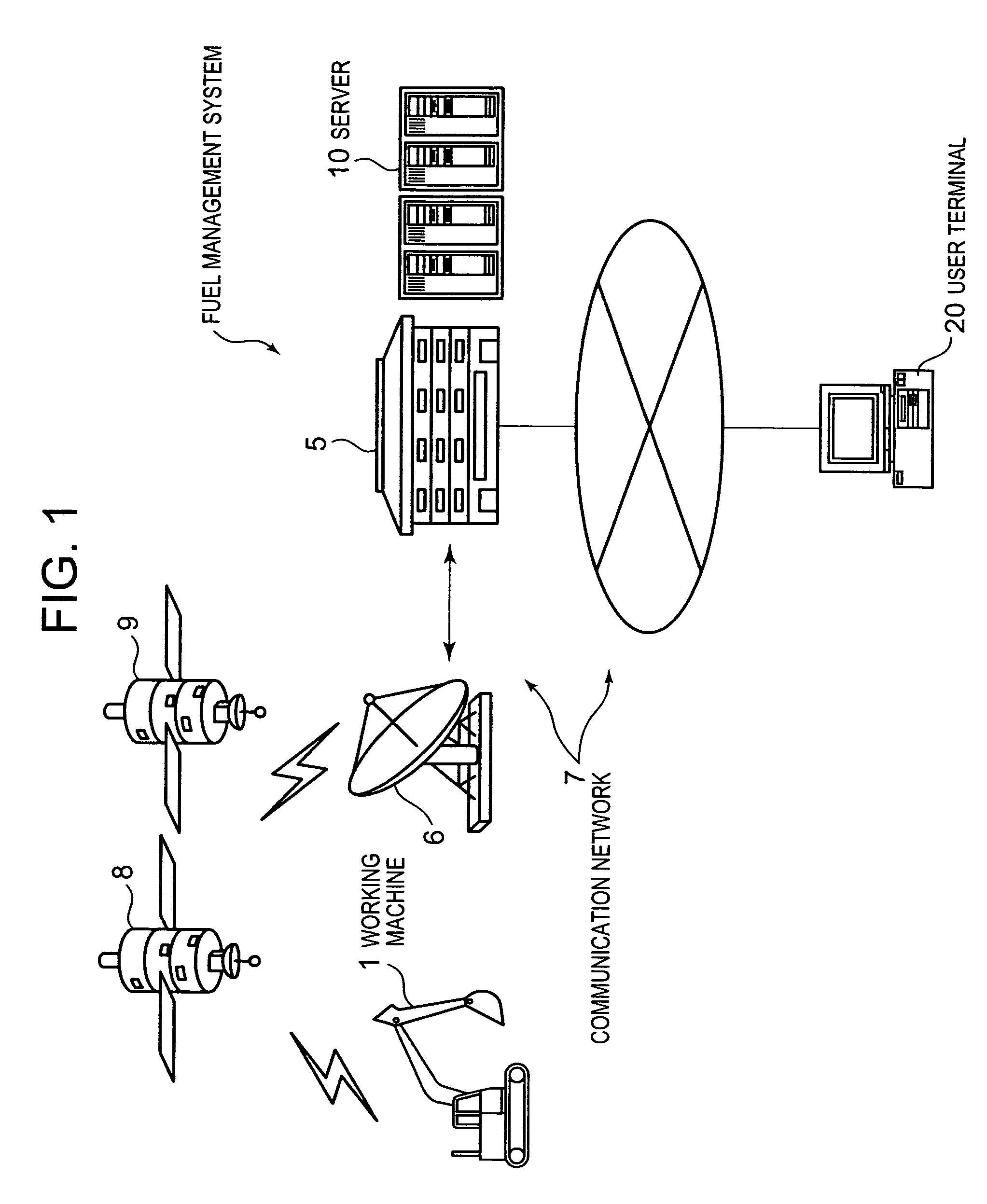
[0021]FIG. 1 is a schematic figure showing the schematic structure of a fuel management system of a working machine according to this embodiment.
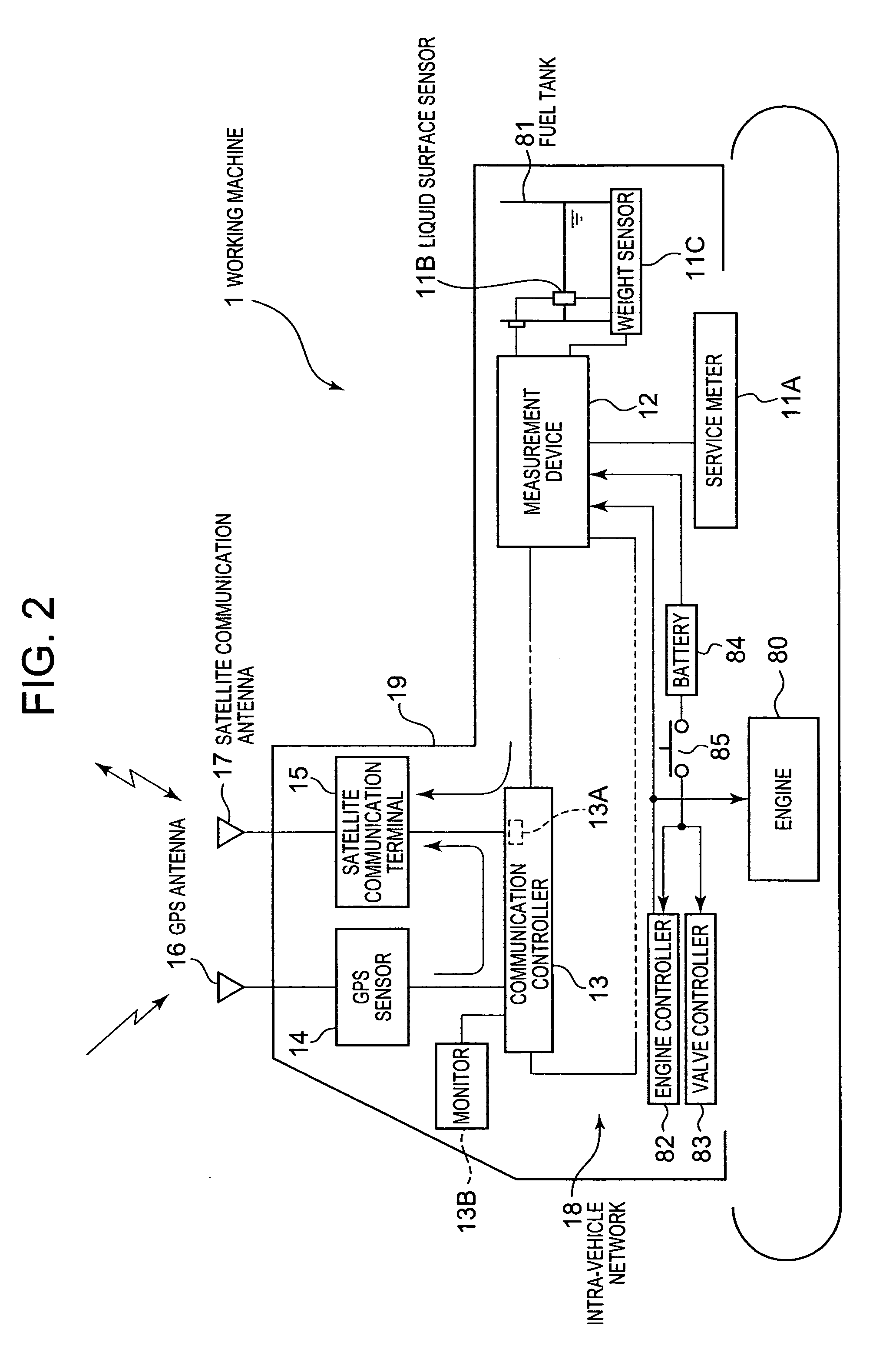
[0022] The fuel management system of this embodiment is arranged to decide if there has been theft of the fuel of a working machine 1, and, if theft has taken place, to issue an alarm. This fuel management system reliably detects whether fuel has been extracted during the period from the termination of working on one day to the start of working the next day, or refueling has not taken place although refueling was scheduled, or foreign material has been put into the fuel tank in order to conceal the extraction of fuel.
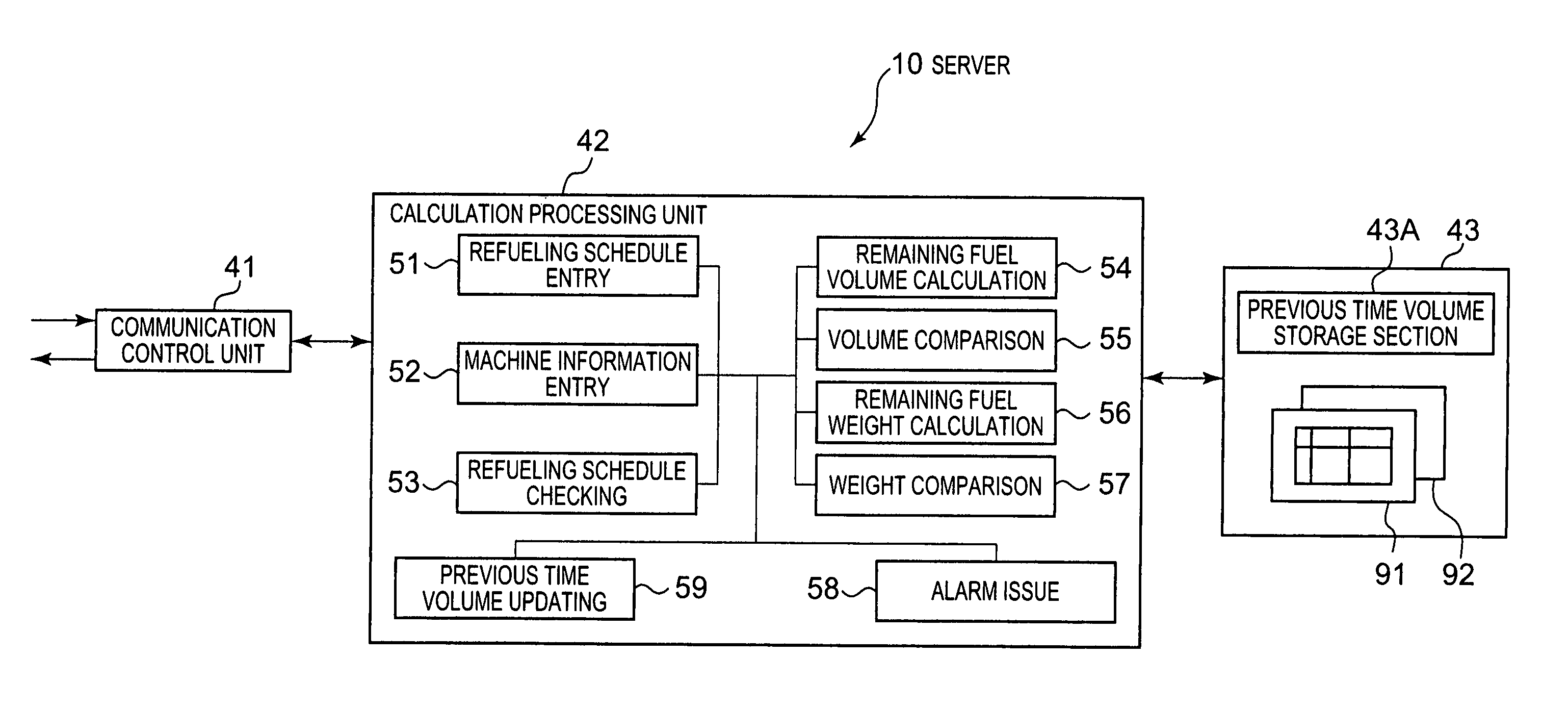
[0023] In FIG. 1, a fuel management system comprises a working machine 1, a server 10 which is provided in a network control bureau 5 on the side of the working machine maker, a user terminal 20 which is provided on the side...
PUM
 Abstract
Description
Claims
Application Information