
Heat treatment equipment and method of driving the same

a heat treatment equipment and heat treatment technology, applied in lighting and heating apparatus, furnaces, muffle furnaces, etc., can solve the problems of many processing problems, leakage, and inability to seal the aperture of the process tub

Inactive Publication Date: 2007-04-12
SAMSUNG ELECTRONICS CO LTD
View PDF4 Cites 18 Cited by
  • Summary
  • Abstract
  • Description
  • Claims
  • Application Information

AI Technical Summary

Benefits of technology

[0014] A feature of the present invention is to provide heat treatment equipment and a method of driving the same capable of precisely sealing a process tube.
[0015] Another feature of the present invention is to provide heat treatment equipment and a method of driving the same in which a tube cap and parts for moving the tube cap are protected from any excessive impact.
[0026] In still other embodiments, the method may further include stopping the driving of the moving unit when the sealing pressure measured by the pressure sensor exceeds a threshold pressure.

Problems solved by technology

However, the conventional vertical heat treatment equipment may cause several problems because the operation for sealing the aperture of the process tube is performed by an encoder value input by the operator.
In this case, the tube cap does not reach a position suitable for sealing the aperture of the process tube, so that a leak may occur.
That is, the aperture of the process tube may not be sealed.
As a result, internal temperature and pressure of the process tube in which the diffusion or deposition process is being performed may not be appropriate, leading to many processing problems.
However, this method may have a problem in that the tube cap may not move to a position suitable for sealing the aperture of the process tube due to, for example, degradation of the gear assembly or the ball screw.
This not only causes excessive impact on the gear assembly engaged with the motor and the ball screw but also may destroy the tube cap which is moved by the gear assembly and the ball screw.

Method used


Image

  • Heat treatment equipment and method of driving the same
  • Heat treatment equipment and method of driving the same
  • Heat treatment equipment and method of driving the same

Examples


Embodiment Construction

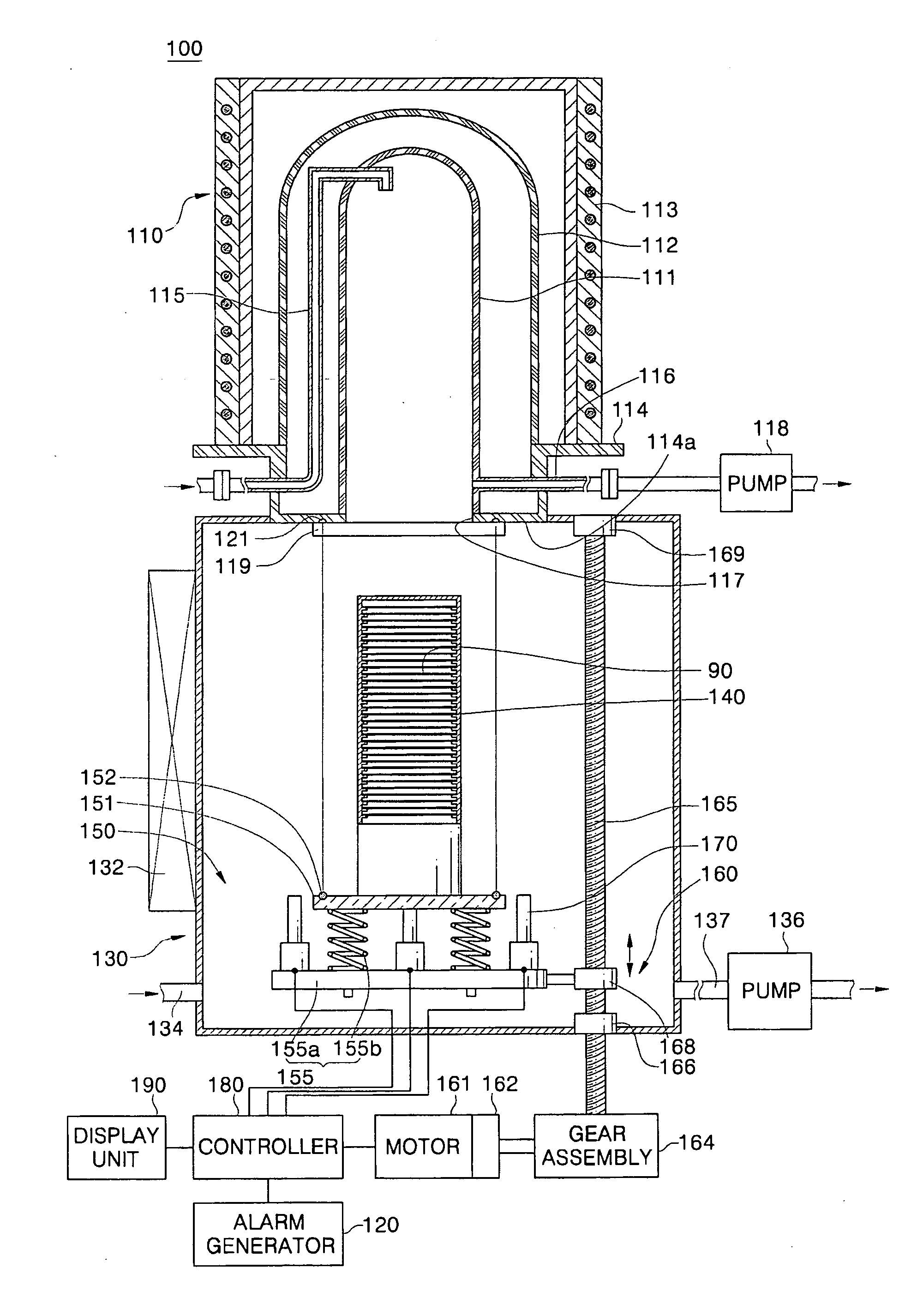
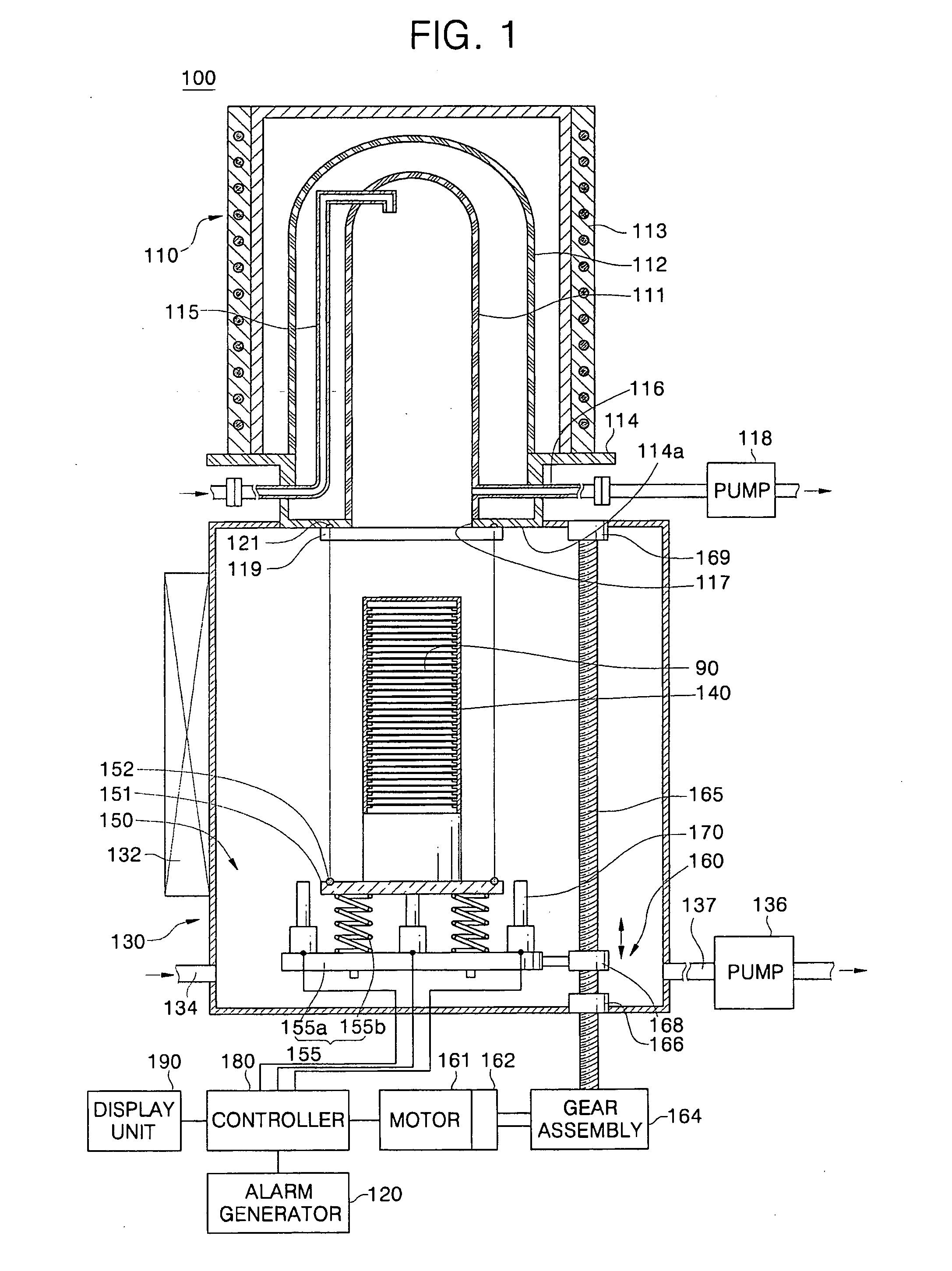
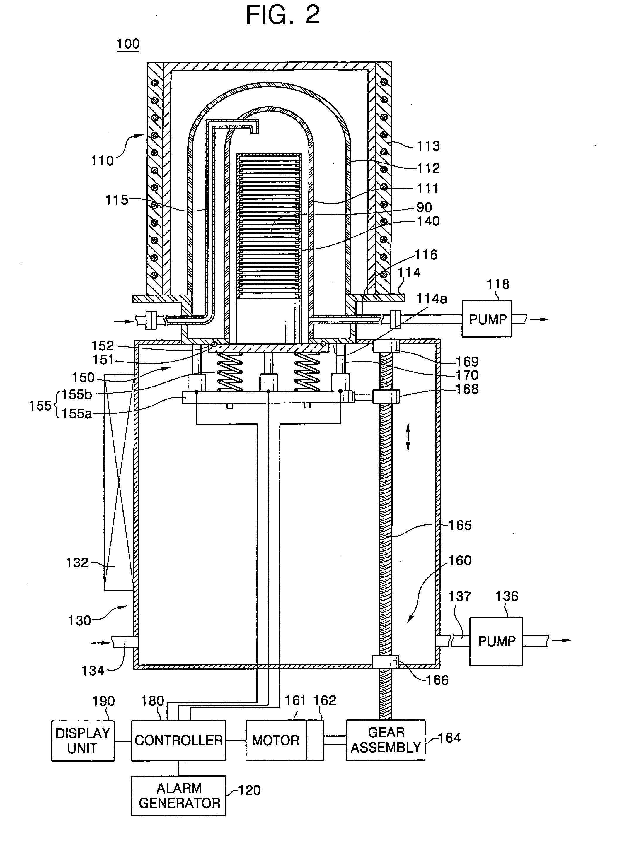
[0033]FIG. 1 is a cross-sectional view of heat treatment equipment according to an exemplary embodiment of the present invention, FIG. 2 is a cross-sectional view illustrating the state in which a process tube of the heat treatment equipment of FIG. 1 is normally sealed, FIG. 3 is a cross-sectional view illustrating the state in which the process tube of the heat treatment equipment of FIG. 1 is overly sealed, FIG. 4 is a perspective view of a sealing unit of the heat treatment equipment of FIG. 1, and FIG. 5 is a flowchart illustrating a method of driving the heat treatment equipment according to an exemplary embodiment of the present invention.

[0034] Referring to FIGS. 1 to 4, the heat treatment equipment 100 of the present invention includes a process tube 110 for providing a space for a heat treatment process, a load lock chamber 130 connected to the process tube 110 to provide a space for a boat 140 on which a wafer 90 is loaded, and a shutter 119 arranged between the process ...


PUM

PropertyMeasurementUnit
sealing pressureaaaaaaaaaa
pressureaaaaaaaaaa
pressure sensoraaaaaaaaaa

Abstract

Heat treatment equipment and a method of driving the same are provided. The heat treatment equipment includes: a process tube having an aperture at one side thereof; a sealing unit for opening or closing the aperture; and a pressure sensor for measuring sealing pressure between the sealing unit and the one side of the process tube. In the heat treatment equipment, the aperture of the process tube can be sealed according to the sealing pressure of the sealing unit so that the process tube can be precisely sealed.

Description

[0001] This U.S. nonprovisional patent application claims priority under 35 U.S.C. §119 of Korean Patent Application 2005-93072 filed on Oct. 4, 2005, the entire contents of which are hereby incorporated by reference. BACKGROUND OF THE INVENTION [0002] 1. Field of the Invention [0003] The present invention relates to equipment and a method for manufacturing a semiconductor device, and more particularly, to heat treatment equipment for processing a wafer through a heat treatment process and a method of driving the same. [0004] 2. Description of Related Art [0005] Generally, semiconductor devices are manufactured by repeatedly performing various processes such as photolithography, diffusion, deposition, etching, metallization, etc. on a semiconductor substrate made of pure silicon. [0006] Of these manufacturing processes, diffusion and deposition processes are performed by a heat treatment process at a high temperature. Heat treatment equipment for performing the heat treatment proces...

Claims


Application Information

Patent Timeline
Patent Type & Authority Applications(United States)
IPC IPC(8): H05B7/18
CPCF27B5/04F27B17/0025F27D5/0037H01L21/67109H01L21/67126H01L21/67757H01L21/324
Inventor SEO, DAE-MANLEE, JANG-HYEOKKIM, DAE-WOO
Owner SAMSUNG ELECTRONICS CO LTD
Learn More