System and method for an adaptive synchronous switch in switching regulators

Active Publication Date: 2007-04-12
ACTIVE SEMI
View PDF10 Cites 20 Cited by
  • Summary
  • Abstract
  • Description
  • Claims
  • Application Information

AI Technical Summary

Benefits of technology

[0045] A system is also provided for adaptively compensating for the offset and delay of a comparator in a switching regulator to thereby achieve a more optimal on/off timing of a synchronous switch that is controlled by the comparator in a feedback control loop. In one embodiment thereof, the system includes a sampling feedback unit that samples at least one a node in the output of the switching regulator and generates at least one sampled error signal, a feedback analysis unit that determines if the current comparator offset is too high or too low relative to a target switching regulator output value, the feedback analysis unit receiving the sampled error signal value as an input and, based at least in part thereupon, outputs an offset determination signal, and a feedback compensation unit, which receives the sampled error signal and the offset determination signal as inputs, and, based at least in part thereupon, and generates as an output a compensated feedback error signal, the compensated feedback error signal being communicated as a feedback input to the comparator such that the compensated feedback error signal is operable as a comparator offset adjustment signal that results in more optimal comparator control output timing of the on and off times of the synchronous switch and thereby improve convergence towards the target switching regulator output value and lower the next

Problems solved by technology

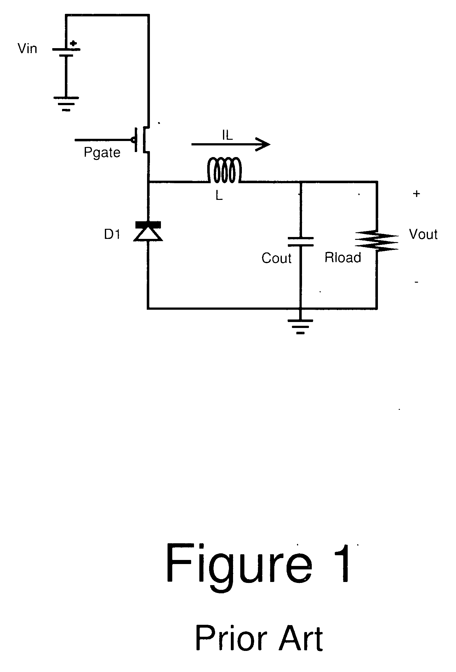
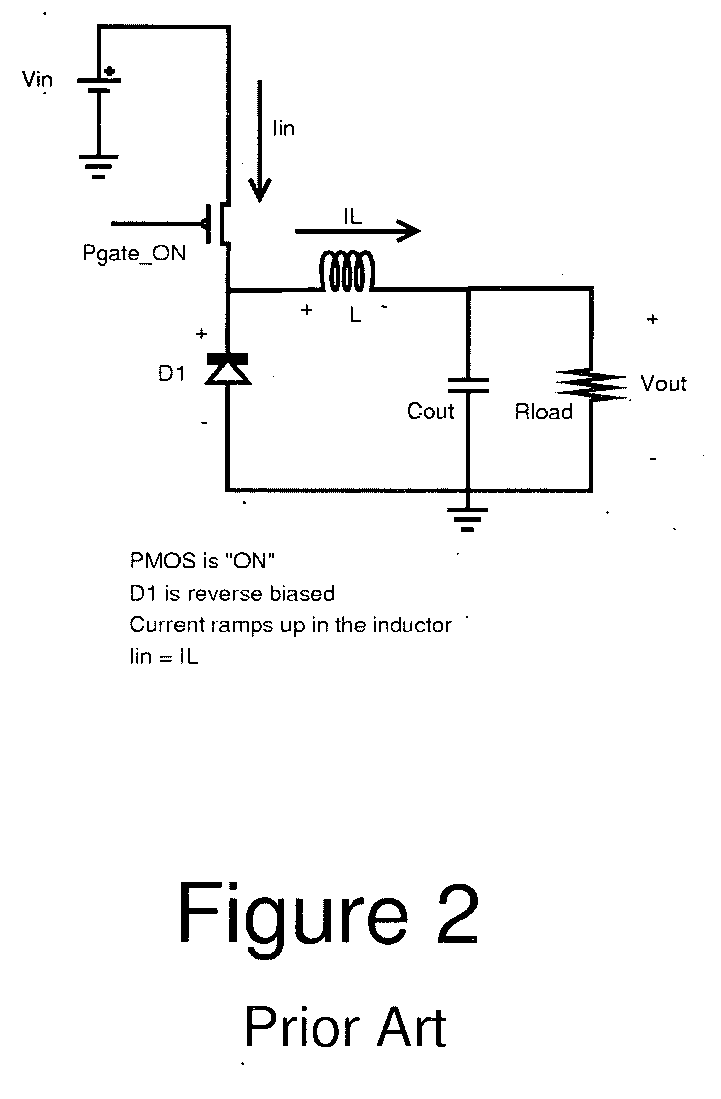
A problem with using the catch diode for buck controllers, and other switching controllers in general, is that the inherent voltage drop across the catch diode multiplied by the current through the diode wastefully dissipates a significant amount of power.
This power dissipation can be unacceptable in certain applications.
For buck converters with high Vin/Vout ratios the problem is more acute because the time the PMOS is on (i.e., PMOS duty cycle) becomes shorter; this means that current flows through the diode for a greater proportion of each cycle.
If the current spends more of its time flowing through the diode, the current also spends more of its time dissipating power in the diode, which brings down the overall system efficiency.
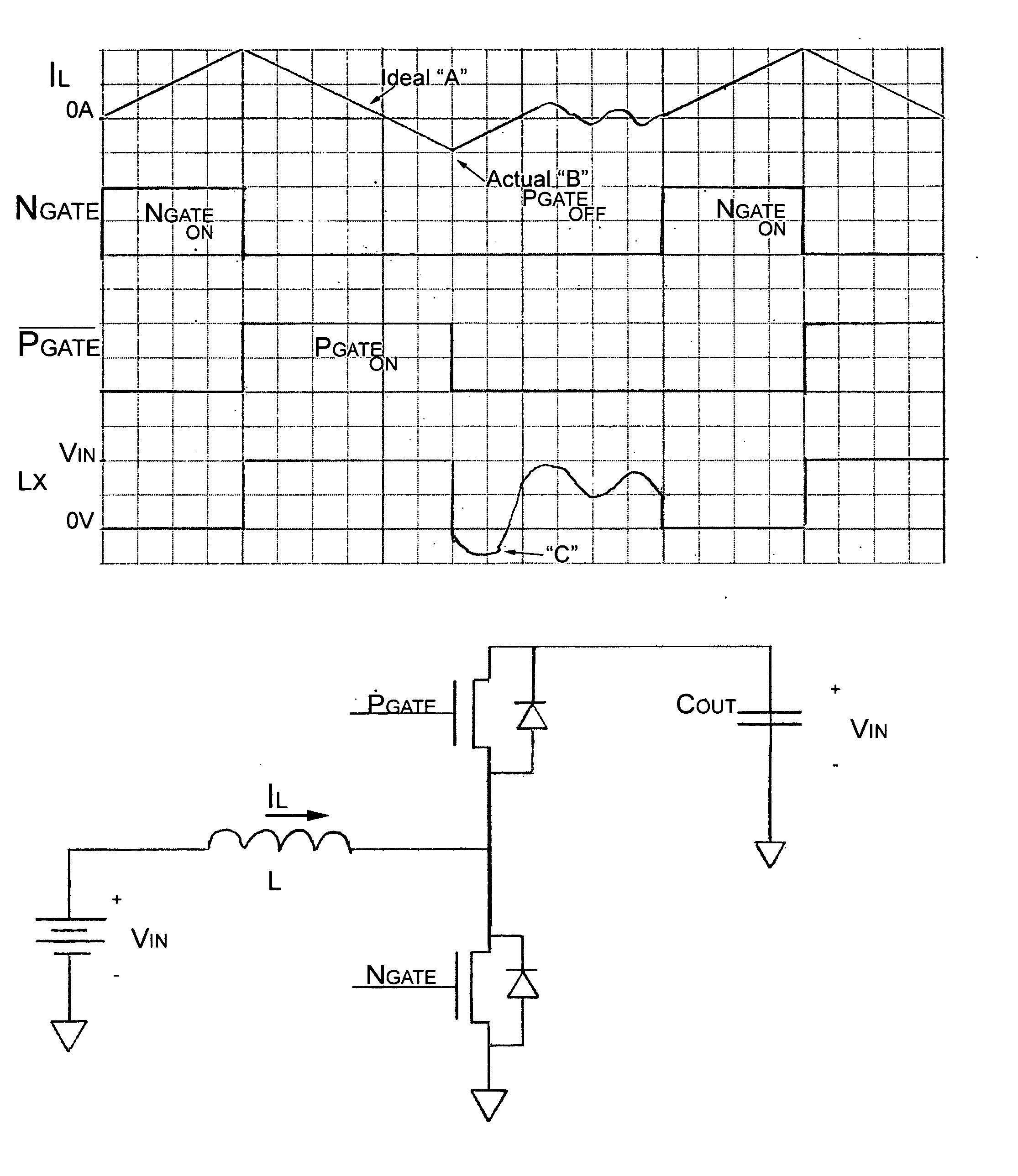
Comparator offset voltages and finite response times do limit the usefulness of the perfect diode schemes.
The drawbacks become more acute as switching frequencies increase because the time available to make an accurate comparison becomes shorter.
The non-zero inductor current left over in the inductor will cause increased ringing when both FETs are turned off.
It also increases power dissipation

Method used


Image

  • System and method for an adaptive synchronous switch in switching regulators
  • System and method for an adaptive synchronous switch in switching regulators
  • System and method for an adaptive synchronous switch in switching regulators

Examples


Embodiment Construction

[0049] The present invention is best understood by reference to the detailed figures and description set forth herein.

[0050] Embodiments of the invention are discussed below with reference to the Figures. However, those skilled in the art will readily appreciate that the detailed description given herein with respect to these figures is for explanatory purposes as the invention extends beyond these limited embodiments. For example, it should be appreciated that those skilled in the art will, in light of the teachings of the present invention, recognize a multiplicity of alternate and suitable approaches, depending upon the needs of the particular application, to implement the functionality of any given detail described herein, beyond the particular implementation choices in the following embodiments described and shown. That is, there are numerous modifications and variations of the invention that are too numerous to be listed but that all fit within the scope of the invention. Als...


PUM


Abstract

Techniques for an adaptive synchronous switch in switching regulators are described, one aspect of which is to achieve a more optimal on/off timing of a synchronous switch that is controlled by the comparator in a feedback control loop and thereby improves power conversion efficiency and system performance; One approach samples a node in the output of the switching regulator and generates a sampled error signal that is analyzed to determine if the current comparator offset is too high or too low relative to a target switching regulator output value at least in part based on the sampled error signal value, and accordingly generates a compensated feedback error signal and applied to the compensated feedback error signal to an input of the comparator to have the effect of a comparator offset adjustment signal.

Description

CROSS-REFERENCE TO RELATED APPLICATIONS [0001] The present Utility patent application claims priority benefit of the U.S. provisional application for patent No. US60 / 725,144, filed one Oct. 11, 2005 under 35 U.S.C., and entitled “Adaptive Synchronous Switch for Switching Regulators” 119(e). The contents of this related provisional application are incorporated herein by reference.FEDERALLY SPONSORED RESEARCH OR DEVELOPMENT [0002] Not applicable. REFERENCE TO SEQUENCE LISTING, A TABLE, OR A COMPUTER LISTING APPENDIX [0003] Not applicable. COPYRIGHT NOTICE [0004] A portion of the disclosure of this patent document contains material that is subject to copyright protection. The copyright owner has no objection to the facsimile reproduction by anyone of the patent document or patent disclosure as it appears in the Patent and Trademark Office, patent file or records, but otherwise reserves all copyright rights whatsoever. FIELD OF THE INVENTION [0005] The present invention generally relate...

Claims


Application Information

Patent Timeline
IPC IPC(8): G05F1/00
CPCH02M3/1588Y02B70/1466Y02B70/10H02M1/0009
Inventor GRAY, RICHARD LANDRYHUYNH, STEVEN
Owner ACTIVE SEMI
Why Eureka
Try Eureka