Method and apparatus for forming optical articles

Inactive Publication Date: 2007-04-12
AKONIA HOLOGRAPHICS
View PDF47 Cites 9 Cited by
  • Summary
  • Abstract
  • Description
  • Claims
  • Application Information

AI Technical Summary

Benefits of technology

[0027] The adherent may be applied in a continuous layer. The adherent may include a photocurable adherent. The adherent may have a refractive index within one percent of the average refractive indices of the first substrate and the second substrate. The adherent may be cured utilizing thermal or radiation energy. The use of heat may be used to accelerate curing of the adherent.

Problems solved by technology

Such divots or peaks typically cause rapid variations in thickness measurements taken at different locations along a substrate and may therefore skew an rms measurement.
Clearly, these characteristics often cause numerous difficulties when attempting to form structures with combinations of low surface smoothness variations, low thickness uniformity variations, and / or low bow.
It is difficult to prepare or obtain substrates or multi-layer articles having such properties.
Such chemical / mechanical polishing, however, is expensive and time-consuming, and may still be inadequate for preparing substrates and articles having the above properties.
The down time of the apparatus required to measure and adjust the optical flats to the desired parallel relationship increases the cost and time of production.

Method used


Image

  • Method and apparatus for forming optical articles
  • Method and apparatus for forming optical articles
  • Method and apparatus for forming optical articles

Examples


example i

[0104] A multi-layer optical media package was fabricated in a first example by the following steps. An optical flat was utilized with an outer diameter measuring 150 mm, a thickness of 25.4 mm, surface flatness of 0.1 waves / cm, and with etched vacuum grooves at 127 mm and 25.4 mm diameters. The vacuum grooves are about 1 mm in width and about 0.5 mm in depth. The optical flats were placed in a mechanical mount that statically held the outer rim of the optical flats flush while holding the bottom flat level. The bottom flat is then fitted with a retainer that holds 3 spacer balls at 120° increments around the outer rim. The spacer balls are AFBMA Grade 25 standard made of single crystal sapphire with a diameter of 3.000 mm. The flats were then cleaned using the drag and drop technique with methanol.

[0105] A glass substrate with an outer diameter of 130 mm, an inner hole with a diameter of 15 mm, and 0.7 mm thick was then cleaned using the same technique described above and placed c...

example ii

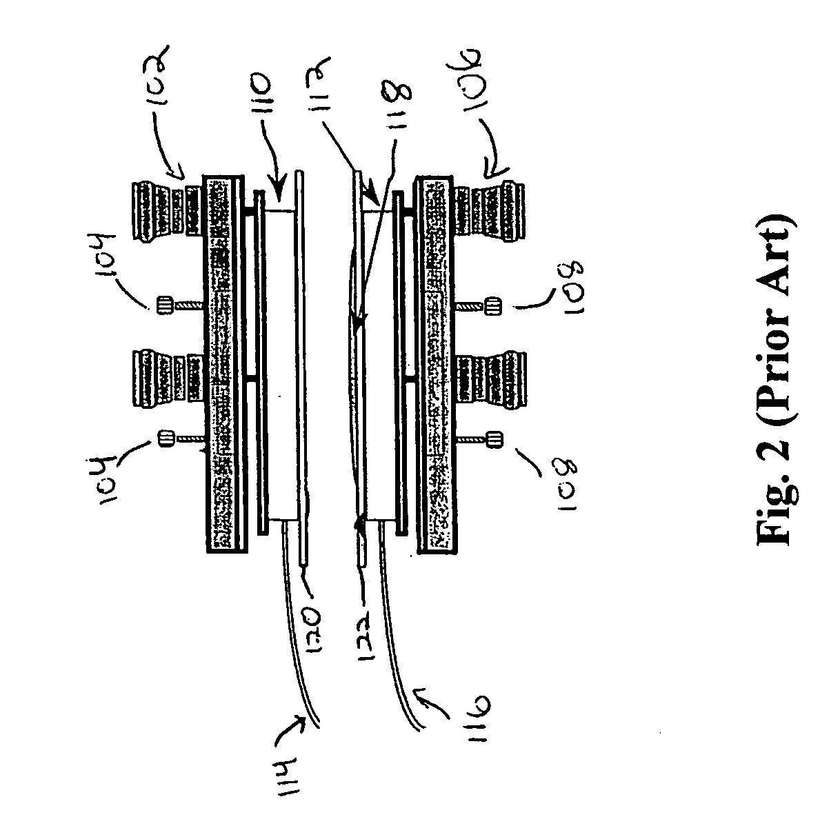
[0107] A multi-layer optical media package was fabricated by the following steps. An optical flat was utilized with an outer diameter measuring 101.6 mm, with a thickness of 25.4 mm, surface flatness of 0.1 waves / cm, with etched grooves of an inner diameter of 6.4 cm. These grooves are 3.2 mm wide by about 1.6 mm deep. Square glass substrates of display glass measuring 75 mm by 75 mm were cleaned and placed on each of the optical flats according to the method of the first example. The outer edge of the substrates and the spacer balls are held with a mechanical mount (e.g., see FIG. 3) that is incorporated with the optical flats. Matrix resin was then pooled on the bottom substrate and the top substrate was then lowered slowly an angle till surface contact was made. The top flat was then hinged slowly until it made contact with each of the spacer balls. The apparatus was then left until the matrix resin at least partially hardened. The vacuum was then released and the media package w...


PUM


Abstract

A method and apparatus for fabricating a multi-layer optical article includes grasping an outer surface of a first substrate with a first holder, whereby the outer surface of the first substrate is held to an inner surface of the first holder, grasping an outer surface of a second substrate with a second holder, whereby the outer surface of the second substrate is held to an inner surface of the second holder, arranging the inner surfaces of the holders to face one another, arranging at least one spacer element between the holders, disposing an adherent on the inner surface of one of the substrates, moving the holders together such that the holders contact the at least one spacer and the substrates contact the adherent, and at least partially curing the adherent while the inner surfaces of the holders are in a selected angular relationship.

Description

TECHNICAL FIELD [0001] The present invention relates generally to multi-layer optical articles, and more specifically to improved methods and apparatuses for forming multi-layer optical articles with improved optical properties. BACKGROUND [0002] Many optical systems require devices having specific optical properties, in particular, surface flatness, thickness uniformity, and / or bow. Surface flatness of an article is determined by measuring the variation of the article's surface from a specified surface profile (the profile, for example, may have a certain bow). The thickness uniformity is measured by the article's variation from a specified thickness or profile (e.g., parallel or wedge-shaped). Both of these parameters are typically measured in units of optical waves of variation from the specified profile per transverse distance, e.g., waves / cm, where the wave is a specified wavelength, e.g., of the particular light being used for measurement or for the ultimate use. When used her...

Claims


Application Information

Patent Timeline
IPC IPC(8): B32B1/00
CPCG03H1/181G03H2250/37G11B7/0065Y10T428/24628G11C13/04G11C23/00G11B7/24044
Inventor WADE, JAMES J.SISSOM, BRADLEY J.IHAS, BENJAMIN C.MICHAELS, MARK D.TACKITT, MICHAELRILEY, BRIANDHAR, LISACURTIS, KEVIN R.
Owner AKONIA HOLOGRAPHICS
Why Eureka
Try Eureka