Wind blade mould including a heating system

Active Publication Date: 2012-07-26
GURIT TOOLING (TAICANG) CO LTD
View PDF33 Cites 5 Cited by
  • Summary
  • Abstract
  • Description
  • Claims
  • Application Information

AI Technical Summary

Benefits of technology

[0033]If pure ethylene glycol is used for the mould heating, the user may obtain the following novel advantages:
[0035]2. Any spills can be cleaned up easily with water.

Problems solved by technology

However, such known mould incorporating heating systems are thermally inefficient, complex and expensive to manufacture.
However this has the following disadvantages:1. In winter time, the water can freeze, destroying the piping in the mould.2. The water can cause corrosion in the pipes, destroying the mould.3. Without pressure, heating over 90 C cannot be achieved.4. If using pressurized water to achieve higher temperatures, dangerous leakage or explosion can occur.
Effectively this has resulted in the limiting temperature for water boiler systems used for blade mould heating being set at 90 C. Since temperatures up to 80 C are needed for blade production, this causes a longer blade production cycle.
This cannot be achieved with a water heating system.
However using such oil could cause silicone contamination inside the blade workshop.
Silicone contamination would likely provoke failed gluing of the wind turbine blade, or defects in the blade painting.
It is well known that any trace of silicone contamination is extremely harmful to adhesive bonding of all kinds.
In the short history of the wind blade production industry, no other heat transfer fluids have been discovered or used successfully.

Method used


Image

  • Wind blade mould including a heating system
  • Wind blade mould including a heating system
  • Wind blade mould including a heating system

Examples


Embodiment Construction

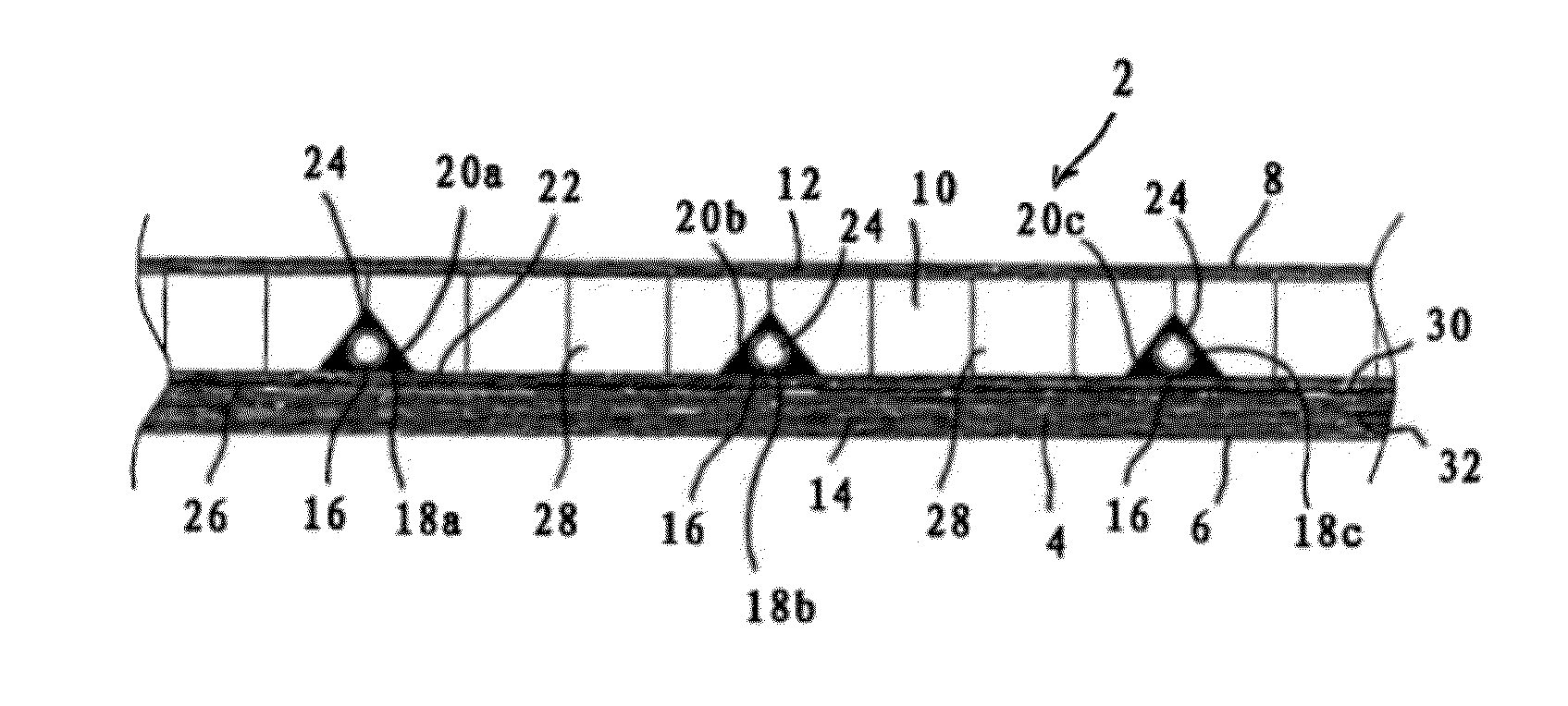
[0053]Referring the Figures, there is shown a mould 2 for moulding a wind turbine blade according to an embodiment of the present invention. FIG. 1 is a schematic cross-section through a part of the mould 2.

[0054]The mould 2 comprises a mould body 4 having a front moulding surface 6 and a rear face 8. The mould body 4 comprises a sandwich construction having a central core layer 10 between rear and front layers 12, 14. The core layer 10 is composed of a lightweight material selected from polymeric foam, for example composed of polyethylene terephthalate, or balsa wood. Typically, the core layer 10 is from 6 to 50 mm thick.

[0055]The rear and front layers 12, 14 are composed of a fiber reinforced resin matrix composite material. The mould of the present invention is not specific with regard to the type of fiber reinforced composite material used for the mould. All mould materials which are known in the art as being typical for the manufacture of polymeric moulds may be employed. The m...


PUM

PropertyMeasurementUnit
Lengthaaaaaaaaaa
Lengthaaaaaaaaaa
Thicknessaaaaaaaaaa

Abstract

A mould for moulding a wind turbine blade, the mould comprising a mould body having a front moulding surface and a rear face, the mould body having at least one tube therein for conveying a heating liquid therethrough, the at least one tube defining a plurality of laterally spaced heating elements, and a continuous layer of heat conductive material located in the thickness direction of the mould body between the plurality of laterally spaced heating elements and the front moulding surface and extending laterally across the space between adjacent heating elements.

Description

TECHNICAL FIELD OF THE INVENTION[0001]The present invention relates to a mould for moulding a wind turbine blade, and a method of moulding a wind turbine blade using such a mould.BACKGROUND OF THE INVENTION[0002]Moulds for moulding a wind turbine blade are known in the art. Wind turbine blades can have a very large surface area, for example a length of up to 60 meters and a width of up to 5 meters. The blade surfaces are typically composed of fibre-reinforced resin matrix composite material which is moulded in the mould. The large mass of resin matrix material to be cured in a curing cycle means that heating of the mould is generally required to accelerate cuing in order to control the curing cycle and ensure uniform and complete resin curing within a commercially acceptable curing cycle time.[0003]It is known to provide tubes within the mould through which a heating fluid is passed to heat the mould surface during the curing cycle. However, such known mould incorporating heating sy...

Claims


Application Information

Patent Timeline
IPC IPC(8): B22D27/04F03D11/00
CPCB29C33/04B29C33/38B29C35/041B29C2033/042B29L2031/085B29L2031/082B29L2031/7498B21D37/16B28B7/42B29C2035/042
Inventor MIRONOV, GABRIEL
Owner GURIT TOOLING (TAICANG) CO LTD
Why Eureka
Try Eureka