
Method of producting a fluorescent optical information carrier and the apparatus and carrier thereof

a technology of fluorescent optical information and equipment, which is applied in the direction of photomechanical equipment, instruments, record information storage, etc., can solve the problems of adding cost to the medium and potential damage to fluorescent dyes during etching, and achieves the effect of low cost and easy practi

Inactive Publication Date: 2007-04-12
KONINKLIJKE PHILIPS ELECTRONICS NV
View PDF5 Cites 4 Cited by
  • Summary
  • Abstract
  • Description
  • Claims
  • Application Information

AI Technical Summary

Benefits of technology

[0014] It is, accordingly, an object of the present invention to provide an easily practiced, low cost process for producing an optical information layer on a substrate and an apparatus enabled to perform the process. The process is especially suited for optical storage discs for which it must be possible to be mass-produced such as read only optical discs (or hybrid discs thereof). The method is targeted for fluorescent optical storage discs that and these discs may be multi layered.
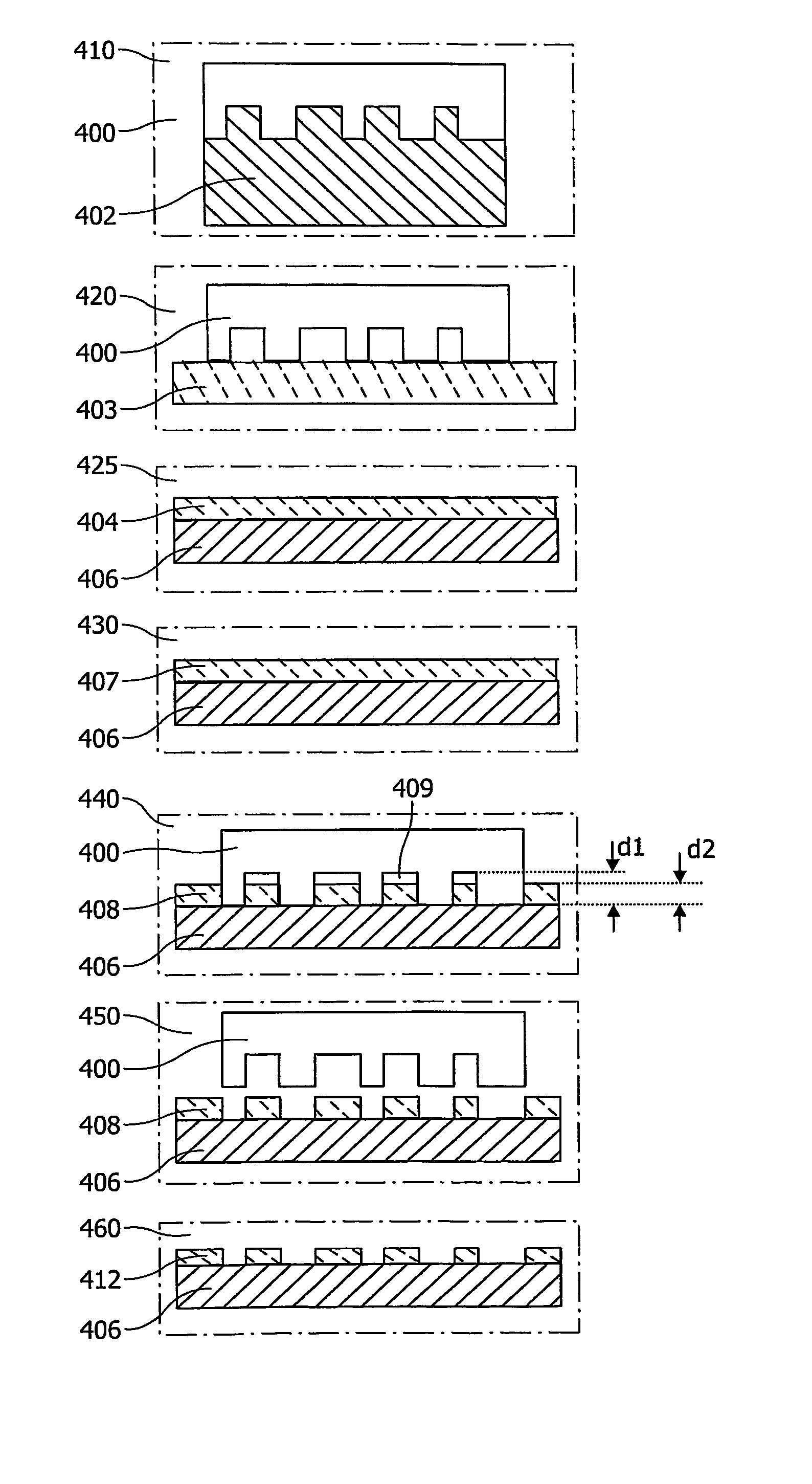
[0016] In order to maximize modulation of the information layer the inventor proposes to structure a fluorescent medium in a way that the layer thickness becomes virtually zero in the land (or pit) areas, whereas it has the required thickness for a strong signal in the remaining areas. For a multi-layer medium the inventor found a strong preference to have the continuous (land) area with zero thickness and the pits with maximum thickness in order to minimize background radiation from different layers.
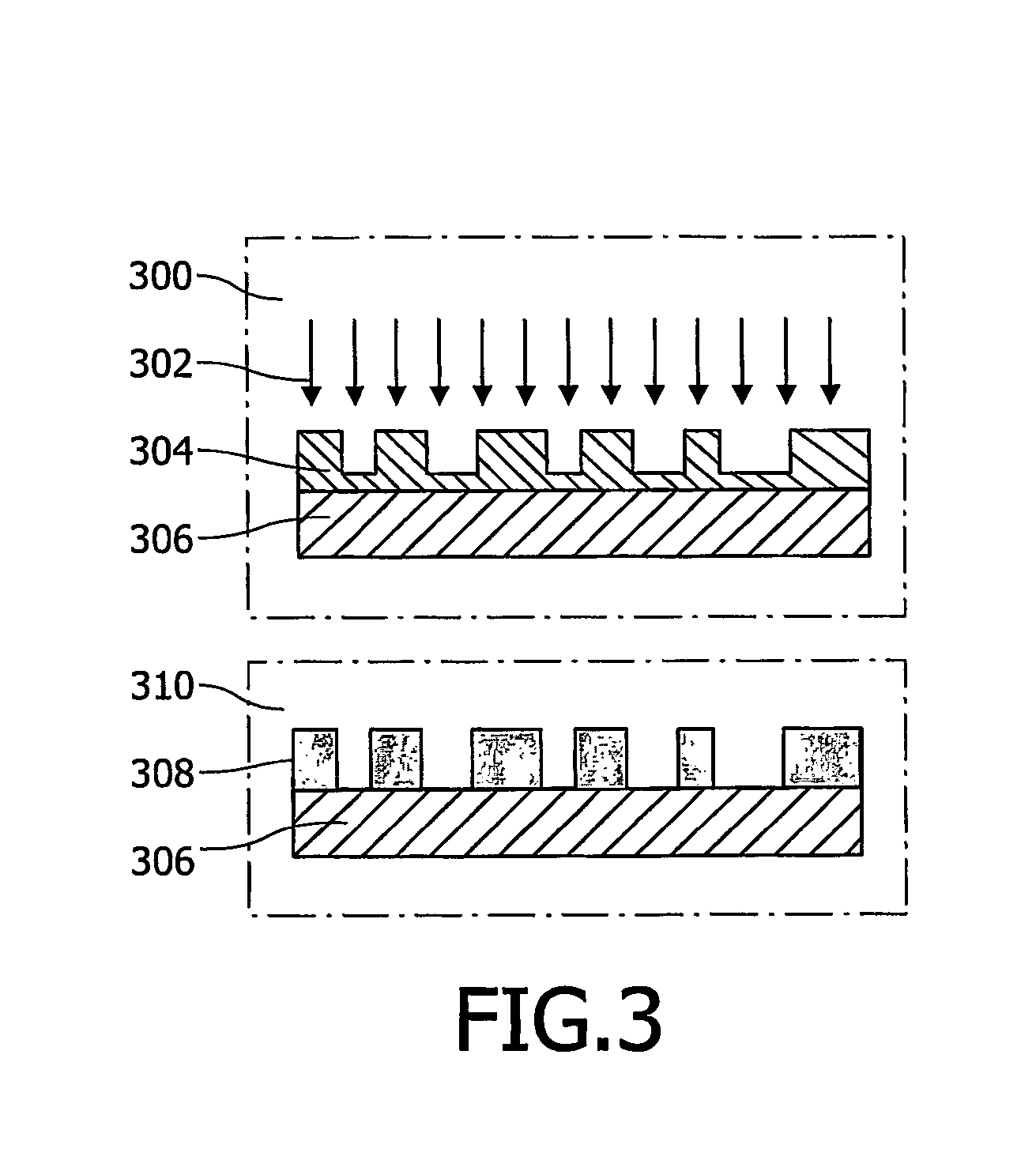
[0017] In one embodiment, e.g., starting from a medium as obtained by the processes (i) and (ii) (as described above and if FIG. 1 and FIG. 2 respectively) the inventor achieved the goal by etching the structured fluorescent layer, for instance in a reactive-ion etcher (RIE). In such a process material is removed from the surface by ion bombardment, as sketched in FIG. 3. It will be removed preferentially in the direction perpendicular to the surface. In this way the lateral resolution of the pattern is not affected. [The etching plasma composition can be chosen such that there is a strong difference in etching rate between the fluorescent layer and the substrate (or a coating applied between substrate and fluorescent layer). In this way the etching will virtually stop at the interface.] The potential disadvantages of this approach are the extra etching steps, which add cost to the medium and the potential damage to the fluorescent dyes during etching.

Problems solved by technology

The potential disadvantages of this approach are the extra etching steps, which add cost to the medium and the potential damage to the fluorescent dyes during etching.

Method used


Image

  • Method of producting a fluorescent optical information carrier and the apparatus and carrier thereof
  • Method of producting a fluorescent optical information carrier and the apparatus and carrier thereof
  • Method of producting a fluorescent optical information carrier and the apparatus and carrier thereof

Examples


Embodiment Construction

[0029]FIG. 3 shows steps of producing a structured fluorescent layer on a flat substrate by embossing followed by etching in accordance with the invention.

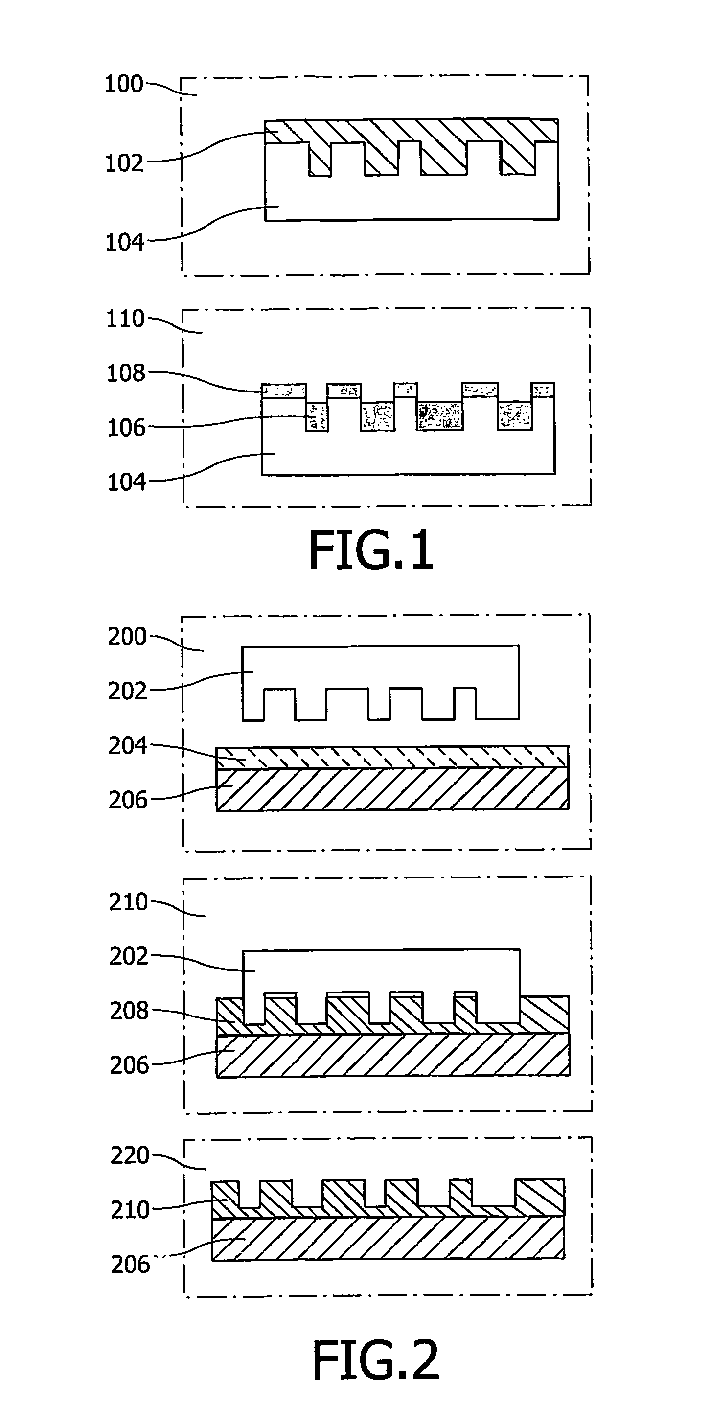
[0030] Step 300 of FIG. 3 starts from a medium as obtained by the processes (i) and (ii) (as described FIG. 1 and FIG. 2 respectively). In step 300, structured fluorescent layer 304 is etched, e.g., in a reactive-ion etcher (RIE). In such a process material from layer 304, which resides on carrier 306, is removed from the surface by ion bombardment. It will be removed preferentially in the direction perpendicular to the surface. In this way the lateral resolution of the pattern is not affected. The etching continues until fluorescent 304 is removed at the pits. The etching plasma composition can be chosen such that there is a strong difference in etching rate between the fluorescent layer and the substrate (or a coating applied between substrate and fluorescent layer). In this way the etching will virtually stop at the interface,...


PUM

PropertyMeasurementUnit
Temperatureaaaaaaaaaa
Thicknessaaaaaaaaaa
Concentrationaaaaaaaaaa

Abstract

The present invention relates to a method of producing high contrast optical storage discs. The method comprises usage of so-called liquid embossing technology process steps that turn out to be beneficial for mass-producing fluorescent optical data storage discs. The present invention also relates to a high contrast optical storage disc comprising an information layer that includes a fluorescent dye on a substrate. The information layer comprises a structure of lands and pits and wherein the lands have a thickness of substantially zero; and the pits have a finite thickness. The optical storage disc may well be multi-layered. The present invention also relates to an apparatus suitable for producing high contrast optical fluorescent storage discs.

Description

FIELD OF THE INVENTION [0001] The present invention relates to a method of manufacturing a fluorescent optical information carrier. [0002] The present invention also relates to a fluorescent optical information carrier. [0003] Moreover the present invention relates to an apparatus for manufacturing a fluorescent optical information carrier. [0004] The present invention is particularly relevant for optical data storage and the production of an optical data storage disc, especially for a high contrast multilayer fluorescent optical disc that can be used as data storage medium. BACKGROUND OF THE INVENTION [0005] In the field of optical recording, increasing the capacity of the information carrier is the trend. An already investigated way for increasing the data capacity consists in using a plurality of information layers in the information carrier. For example, a DVD (Digital Video Disc) can comprise two information layers. Information is recorded on or read from an information layer b...

Claims


Application Information

Patent Timeline
IPC IPC(8): G11B7/24B29C33/56B29C35/08B29C41/00B29C41/04B29C41/08G11B7/24038G11B7/24047G11B7/26
CPCB29C41/003B29C41/045G11B7/263G11B7/24038G11B7/24047B29C41/085G11B7/246G11B7/26B29C41/04
Inventor WIMMBERGER-FRIEDL, REINHOLDSAALMINK, MILANDECRE, MICHEL MARCEL
Owner KONINKLIJKE PHILIPS ELECTRONICS NV
Learn More