3D miniature preconcentrator and inlet sample heater

a preconcentrator and sample heater technology, applied in the direction of component separation, withdrawal sample device, material testing goods, etc., can solve the problems of low surface area to volume ratio of preconcentrator, inability of analytical instruments to detect molecules in such low concentrations, and long time-consuming to accumulate sufficient quantities of analyte, etc., to achieve low thermal mass and large surface area

Active Publication Date: 2007-04-19
OWLSTONE MEDICAL LTD
View PDF20 Cites 15 Cited by
  • Summary
  • Abstract
  • Description
  • Claims
  • Application Information

AI Technical Summary

Benefits of technology

[0015] A preconcentrator according to the instant disclosure illustratively comprises: a substrate with passageways therethrough; a conductive material, such as a metal, covering the top and bottom of the substrate; a top electrical lead connected to the material on the top of the substrate; a bottom electrical lead connected to the material on the bottom of the substrate; an adsorbent coating disposed on top and bottom of the mater

Problems solved by technology

Analytical instruments may not be able to detect molecules in such low concentrations.
These preconcentrators have a low surface area to volume ratio, requiring a long time to accumulate a sufficient quantity of analyte.
Furthermore, due to a pressure drop across the preconcentrator, inline use with existing detectors may require changing the internal air handling.
Such changes can be difficult, expensive and even preclude retrofitting of preconcentrators to an existing device.
The slug is also large requiring a fair amount of time and energy to release the analyte.
This energy consumption poses a particular problem when preconcentrators are used in portable detection systems as it lowers the battery life.
The structure can have thickness in the order of microns and consequently is quite fragile.
The heating element is external to the device, limiting thermal efficiency.
A break in the structure, which also serves as the heating track, will ordinarily cause complete failure.
As a result, suc

Method used


Image

  • 3D miniature preconcentrator and inlet sample heater
  • 3D miniature preconcentrator and inlet sample heater
  • 3D miniature preconcentrator and inlet sample heater

Examples


Embodiment Construction

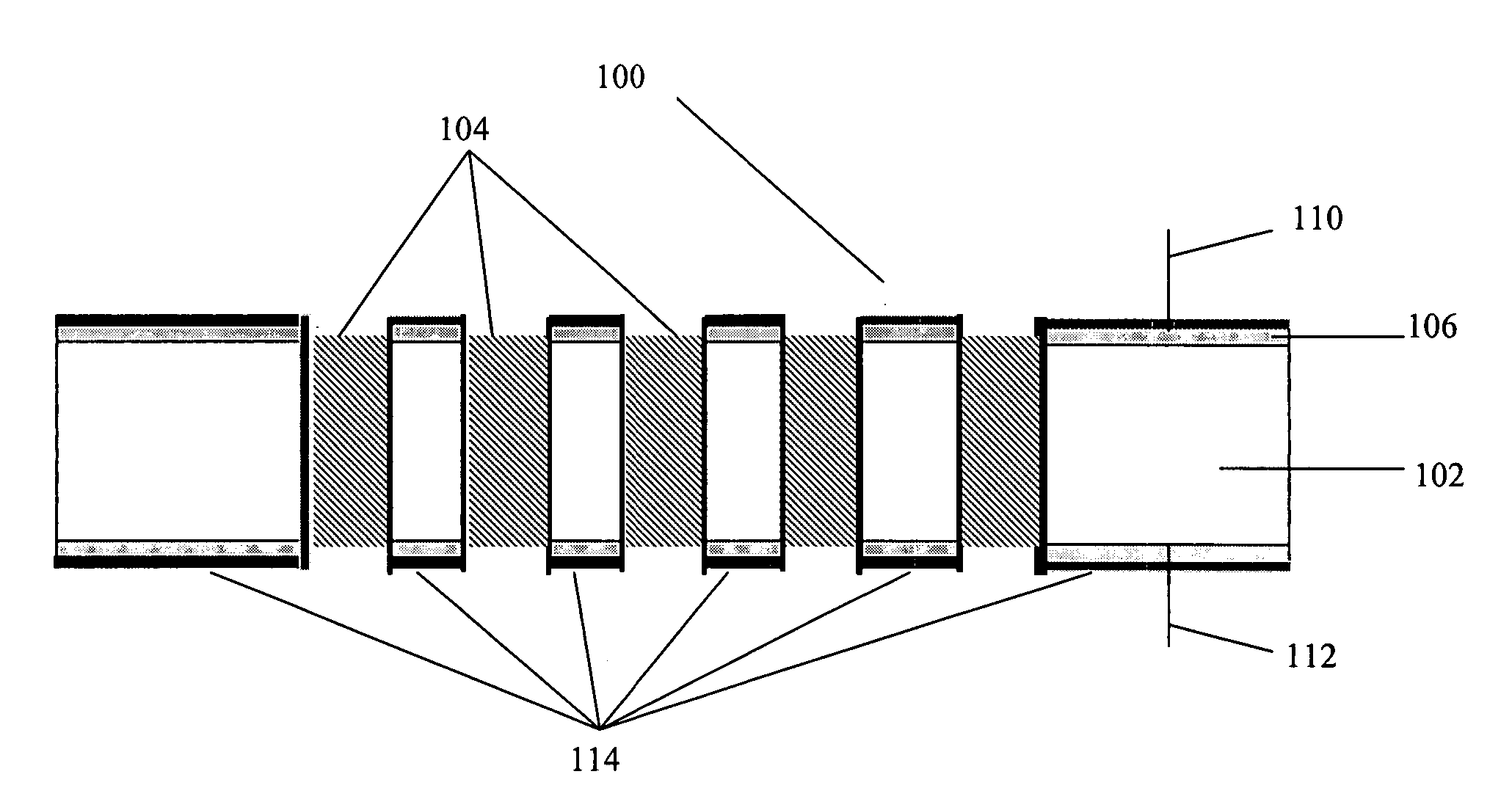
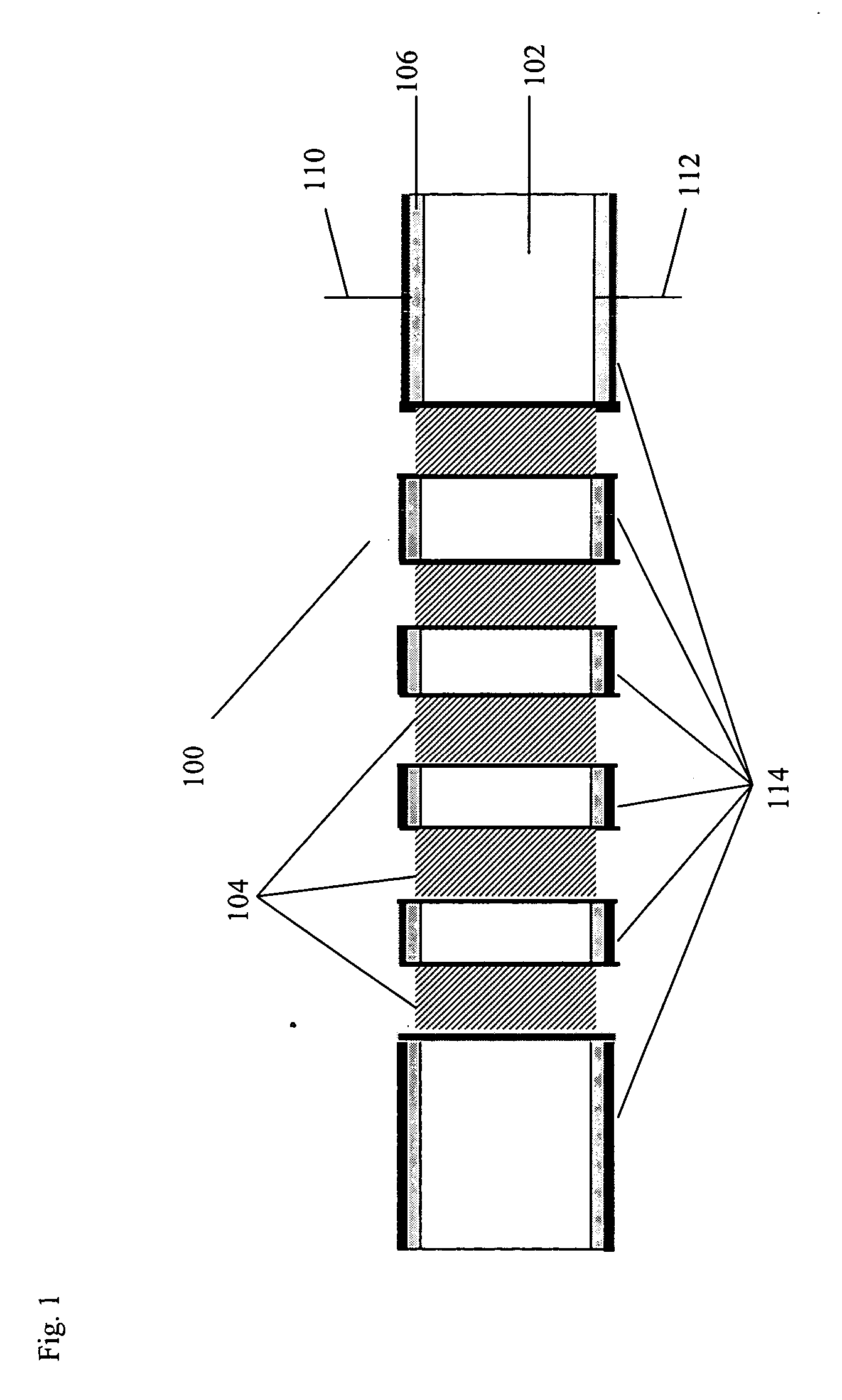
[0029] Reference will now be made in detail to the preferred embodiments of the present invention, examples of which are illustrated in the accompanying drawings. FIG. 1 is a cross-sectional diagram of a preconcentrator 100 according to an embodiment of the present invention. The preconcentrator 100 includes a substrate 102, illustratively, a rectangular parallelipiped, with passageways 104 running between top and bottom major surfaces, a conductive material 106 covering the top and bottom major surface, except for the passageways, a top electrical lead 110, a bottom electrical lead 112, and an adsorbent coating 114 on the outer surfaces of electrical leads 110, 112. Top electrical lead 110 is connected to conductive material 106 on the top side of the substrate. Bottom electrical lead 112 is connected to conductive material 106 on the bottom side of the substrate. Electrical leads 110, 112 provide for passage of current through the conductive material and substrate so that the enti...


PUM


Abstract

The present invention relates to a three dimensional preconcentrator and inlet heater. The preconcentrator consists of a substrate with passageways, a conductive material coated to the top and the bottom of the substrate and an adsorbent coating covering the entire substrate. This substrate is suspended in a holding frame by a connecting bridge. The preconcentrator may also include a resistor and a proportional-integral-differential controller. The device may be used inline with a detector and can be retrofitted to existing devices. An array of preconcentrators may also be formed. The invention also relates to methods of use of the preconcentrator and methods of manufacture. A method of use includes contacting an analyte and a preconcentrator, allowing the analyte to adsorb to the preconcentrator and then desorbing the analyte. A method of manufacture involves applying the adsorbent coating by misted chemical deposition.

Description

FIELD OF THE INVENTION [0001] The present invention relates to a preconcentrator and inlet sample heater for an analytical instrument. More particularly, the present invention relates to a micro-machined preconcentrator and inlet sample heater with a three-dimensional structure, integral heating, and a semiconductor substrate. BACKGROUND OF THE INVENTION [0002] In analytical chemistry, preconcentrators have been used for many years to collect molecules that are present in low concentrations. Analytical instruments may not be able to detect molecules in such low concentrations. Preconcentrators accumulate and concentrate one or more chemical species of interest over time, so that the analytical instruments can detect the molecule. Thus, preconcentrators increase the sensitivity of analytical techniques such as, e.g., gas chromatography, mass spectrometry, and ion mobility spectrometry (IMS). [0003] Preconcentrators are particularly useful to aid in the detection of trace compounds su...

Claims


Application Information

Patent Timeline
IPC IPC(8): B01D53/02
CPCB01D53/02B01D53/0407Y10T436/25375G01N2030/085G01N1/405
Inventor BOYLE, PAULRUIZ-ALONSO, DAVIDKOEHL, ANDREWRUSH, MARTYNPARRIS, RUSSELLWILKS, ASHLEY
Owner OWLSTONE MEDICAL LTD
Why Eureka
Try Eureka