Method and apparatus for loading catalyst

a technology of catalyst and filling tube, which is applied in the direction of transportation and packaging, packaging goods type, bulk chemical production, etc., can solve the problems of less than optimal catalyst density, voids in the catalyst fill can easily form, and catalyst particles can fracture or crush, so as to reduce the falling velocity of the catalyst and soften the catalyst. the effect of the catalys

Active Publication Date: 2007-04-19
QUANTA ASSOC
View PDF29 Cites 19 Cited by
  • Summary
  • Abstract
  • Description
  • Claims
  • Application Information

AI Technical Summary

Benefits of technology

[0009] Embodiments of the present invention generally relate to methods and apparatus that prevent breakage of a catalyst particle and evenly fill the catalyst into tubes to an optimum density. Particles of catalyst can empty directly down into the tubes in order to obtain quick filling of the tubes. However, a loading tool softens the fall of the catalyst and provides even filling of the tube in order to avoid crushing or breaking of the catalyst and the formation of catalyst voids in the tube. The loading tool comprises a center member, such as a rod, a wire, a chain, or the like with a plurality of damper members shaped in different ways but each having a radial extension smaller than the inner radius of the tube. In operation, the center member can be jerked during the filling operation while simultaneously being lifted up gradually as the tube fills. Alternatively, the center member can remain stationary with its lowest extremity slightly above the anticipated fill level of the catalyst being added. In either type of operation, limited, pre-determined amounts of catalyst are introduced sequentially to allow periodic adjustment of the position of the lowest extremity of the center member. The damper members reduce the falling velocity of the catalyst and divert the catalyst from falling in straight downward paths. This avoids bridge formation of the catalyst particles during filling. The type and shape of the damper member and center member can be adapted in particular cases to the actual type of catalyst particles and the tube diameter. The damper members can be stiff or flexible since they do not occupy a substantial portion of the cross section of the tube at any particular axial location. The height of the lowest extremity of the center member can be periodically adjusted manually by physically feeling the center member change from tension to slackness as the lowest extremity of the center member contacts the catalyst interface. In another embodiment of the present invention, a sensor member can be positioned at a lower portion of the center member to communicate with the top of the center member to provide visual or auditory indication of contact with the catalyst interface.

Problems solved by technology

Voids in the catalyst fill can easily form if catalyst particles are introduced to the tubes too quickly or non-uniformly during the filling of the tubes.
Also, catalyst particles can fracture or crush if they are allowed to free-fall too far during filling of the tubes.
Voids or crushed catalyst create local density variations as well as a catalyst density that is less than optimal.
This results in distortions of gas distribution in a multi-tube reactor and causes uneven temperature distribution over the tubes during operation of the reactor.
The resultant thermal and mechanical stress in the tube can reduce its useful life.
However, this is laborious and delays the filling operation.
Additionally, tapping or vibration can expose the tube to extra mechanical stress.
This adds substantial labor and results in the loss of expensive catalyst
However, there are several disadvantages with this method.
Filling one tube with this method usually requires a number of the socks thereby making the method laborious.
Sometimes, the sock will open prematurely, allowing the catalyst particles to fall a great distance and achieve enough gravimetrically induced velocity to crush or fracture when they hit the bottom of a tube.
Removal of the water and necessary subsequent drying takes a long time.
Additionally, used water requires special treatment, adding time and cost.
Further, the catalyst drops a significant length especially during the first part of the filling operation thereby permitting the catalyst to be crushed or broken during the fall.
Therefore, the particles can pack unevenly over the vertical length of the tube and the filling time can be long.

Method used


Image

  • Method and apparatus for loading catalyst
  • Method and apparatus for loading catalyst

Examples


Embodiment Construction

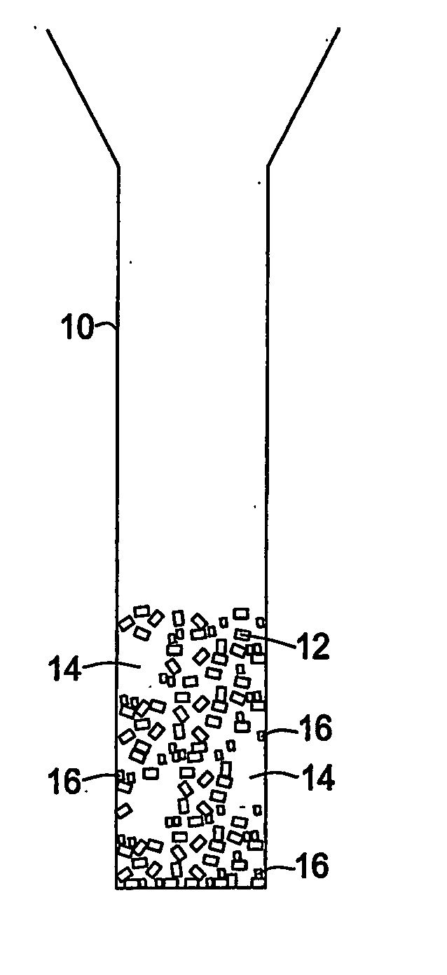
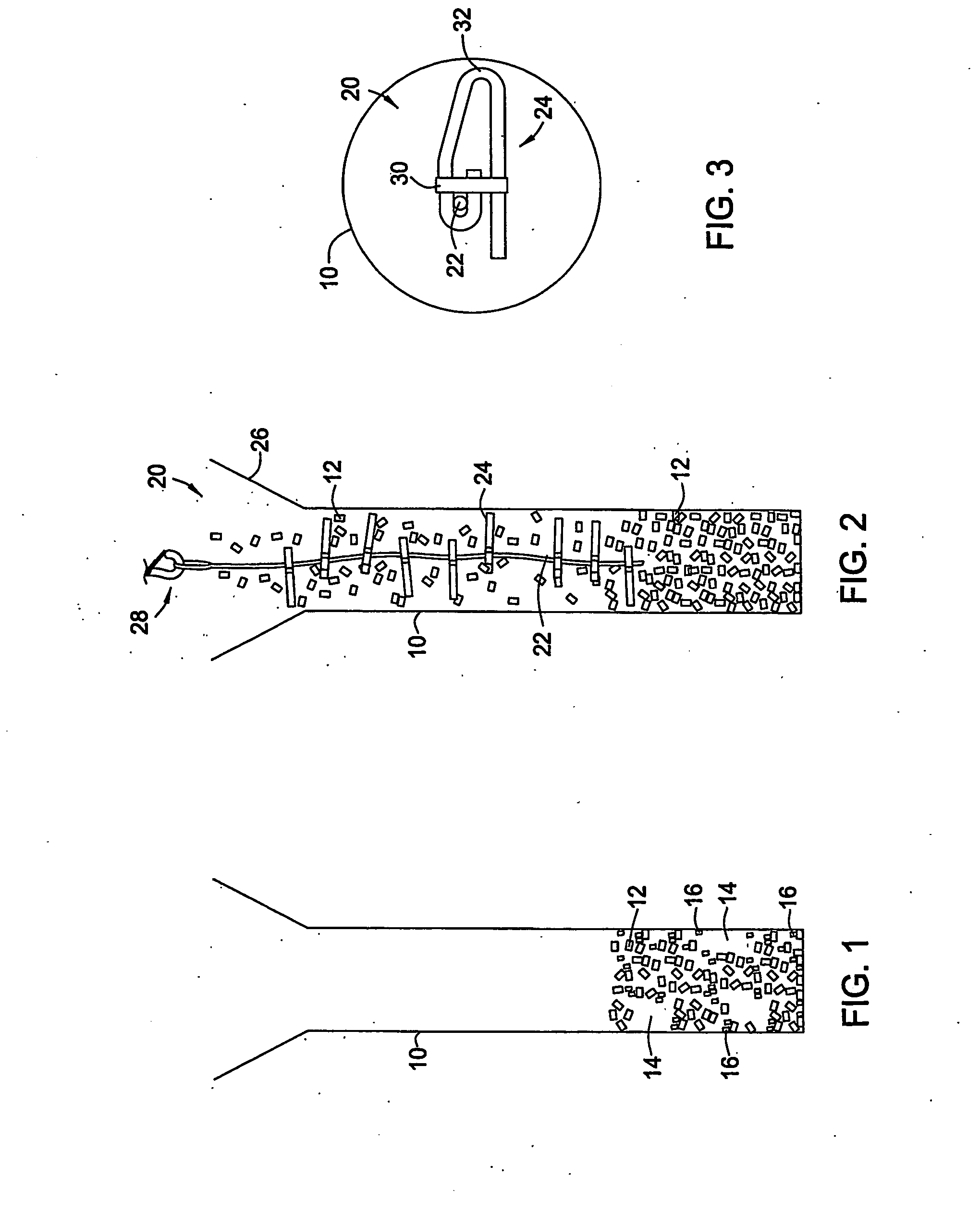
[0014]FIG. 1 shows a tube 10 such as a catalyst tube of a reactor. As illustrated, filling the tube 10 by allowing the particles 12 to fall directly down the tube produces voids 14 and broken particles 16.

[0015]FIG. 2 shows particles 12 such as catalyst falling into a tube 10 that includes a loading tool 20. The loading tool 20 comprises a center member 22 such as a wire, a chain, a rod, or the like and a plurality of damper members 24 substantially transverse and axially arranged on the center member 22 to provide substantially circumferential coverage along a longitudinal length of the tube 10. The center member 22 can be stiff or flexible. The distance between damper members 24 on the center member 22 can be substantially equal or can vary. The plurality of damper members 24 reduces the falling velocity of the particles 12 and diverts the particles from falling in straight downward paths. Since the damper members 24 do not occupy a substantial portion of the cross section of the...


PUM

PropertyMeasurementUnit
diameteraaaaaaaaaa
lengthaaaaaaaaaa
densityaaaaaaaaaa

Abstract

Methods and apparatus are disclosed for filling solid particles into a vertical tube by conveying the particles downwardly into the tube along a loading tool that softens the fall of the particles and provides even filling of the tube. The loading tool includes a center member and a plurality of damper members that can be adapted in particular cases to the actual type of particles and the tube diameter. The damper members can be stiff or flexible since they do not occupy a substantial portion of the cross section of the tube at any particular axial location. In operation, the center member can be jerked during the filling operation while simultaneously being lifted up gradually as the tube fills or it can be sequentially lifted. The damper members reduce the falling velocity of the particles and divert the particles from falling in straight downward paths. This avoids bridge formation and breakage of the particles during filling.

Description

BACKGROUND OF THE INVENTION [0001] 1. Field of the Invention [0002] Embodiments of the present invention generally relate to methods and apparatus for filling particulate material into a tube. More particularly embodiments of the present invention generally relate to methods and apparatus for filling a catalyst into a tube of a primary reformer furnace. [0003] 2. Description of the Related Art [0004] Primary reformer furnaces such as those used in the production of ammonia, hydrogen and methanol typically utilize tens or hundreds of heat transfer tubes that are filled with catalyst particles. These tubes must initially be filled with catalyst, and used catalyst must be replaced with fresh catalyst periodically. Voids in the catalyst fill can easily form if catalyst particles are introduced to the tubes too quickly or non-uniformly during the filling of the tubes. Also, catalyst particles can fracture or crush if they are allowed to free-fall too far during filling of the tubes. Void...

Claims


Application Information

Patent Timeline
Patent Type & Authority Applications(United States)
IPC IPC(8): B65B1/04B01J8/00B01J8/06B65G69/16
CPCB01J8/0015B01J8/003B01J8/06B01J2208/00752B01J2208/00778B65G69/16Y02P20/52
Inventor BRENNOM, STEPHEN
Owner QUANTA ASSOC
Why Eureka
Try Eureka