

Field weakening vector controller for permanent magnet synchronous motor and control module
a synchronous motor and control module technology, applied in the direction of motor/generator/converter stopper, dynamo-electric gear control, motor/generator/converter stopper, etc., can solve the problem of not being able to generate d-axis current commands quickly, unable to ensure high torque accuracy, etc., to achieve high precision and high response
- Summary
- Abstract
- Description
- Claims
- Application Information
AI Technical Summary
Benefits of technology
Problems solved by technology
Method used
Image

Examples
embodiment 1
[0020] (Embodiment 1)
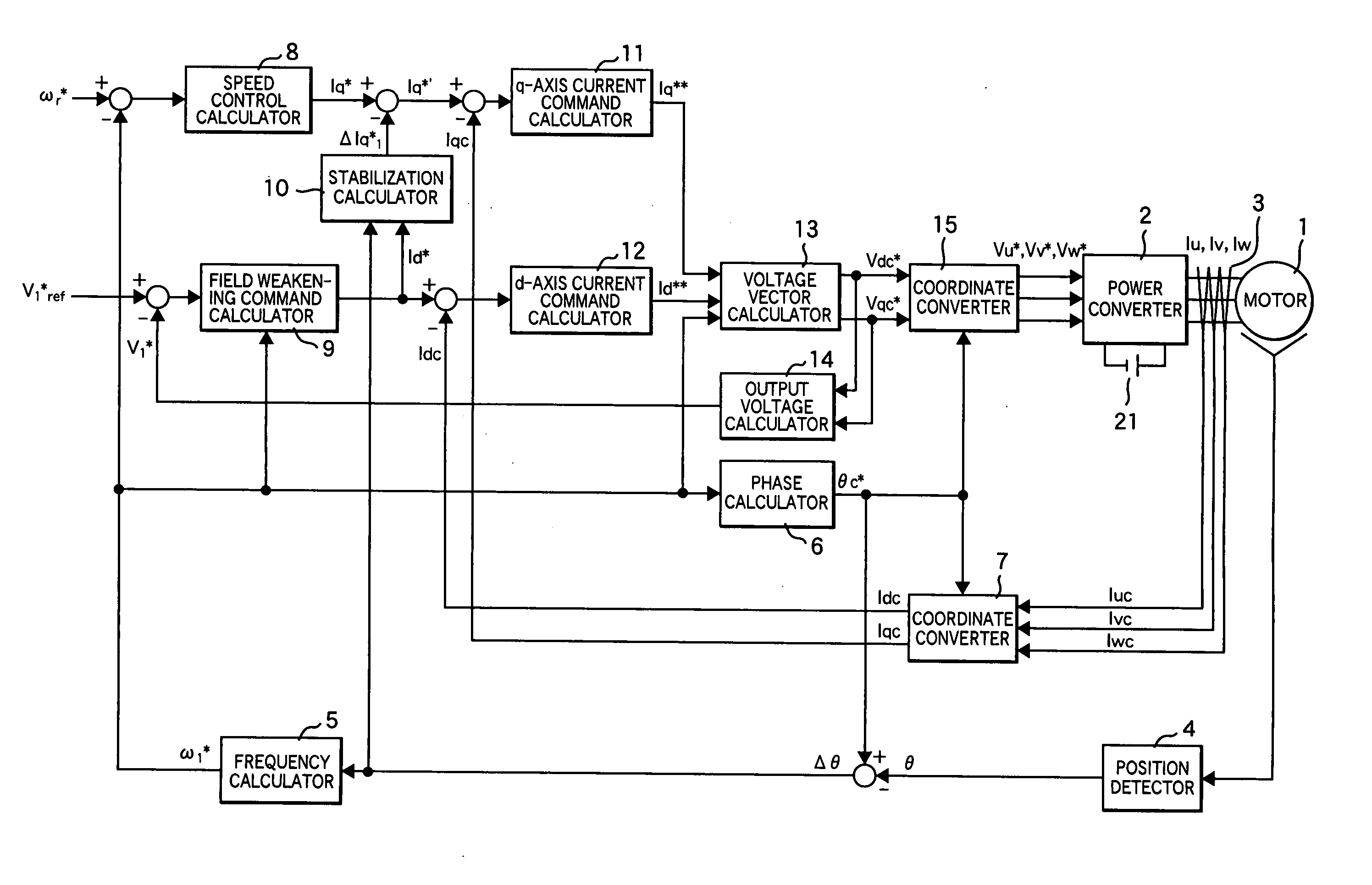
[0021]FIG. 1 shows a schematic diagram of an example of a field weakening vector controller for a permanent magnet synchronous motor which is an embodiment of this invention.
[0022] This example is equipped with the following:
[0023] Permanent magnet synchronous motor 1,
[0024] Power converter 2 which outputs voltages proportional to 3-phase AC voltage command values Vu*, Vv*, and Vw*,
[0025] DC power supply 21,
[0026] Power detector 3 which can detect 3-phase AC currents Iu, Iv, and Iw,
[0027] Position detector 4 made of hall ICs and hall elements to detect motor positions θ,
[0028] Frequency calculator 5 which calculates frequency command value ω1* from axial difference Δθ which is a difference between rotational phase command θc* and position detection value θ,
[0029] Phase calculator 6 which integrates frequency command value ω1* and outputs motor rotation phase command θc*,
[0030] Coordinate converter 7 which inputs detection current values (Iuc, Ivc, and I...
embodiment 2
[0087] (Embodiment 2)
[0088]FIG. 4 shows a schematic diagram of another embodiment of this invention.
[0089] Embodiment 2 is a vector controller of a permanent magnet synchronous motor which uses speed difference (ωr*−ω1*) and d-axis current command value Id* although Embodiment 1 uses axis error Δθ and d-axis current command value Id*.
[0090] Components 1 to 9, 11 to 15, and 21 in FIG. 4 are the same as those of FIG. 1. Stabilization calculator 10′ corrects q-axis current command value Iq* by d-axis current command value Id* and speed difference (ωr*−ω1*) which is a difference between speed command value (ωr* and frequency command value ω1*.
[0091] Assuming that the differential value of axis error Δθ is speed difference (ωr*−ω1*), stabilization calculator 10′ calculates stabilization signal ΔIq*2 using proportional integration gains Kcp and Kci of frequency calculator 5 as expressed by Equation 14. Δ Iq 2*=·(ωr*+ω1*)·(1 / Kci)·s(Kcp / Kci)·s+1·Id*(14)
[0092] Next, stabilization cal...
embodiment 3
[0095] (Embodiment 3)
[0096]FIG. 5 shows a schematic diagram of still another embodiment of this invention.
[0097] Embodiment 3 is a field weakening vector controller of a permanent magnet synchronous motor equipped with d-and q-axis voltage command calculators to which stabilization calculation is applied.
[0098] Components 1 to 10, 14, 15, and 21 in FIG. 5 are the same as those of FIG. 1.
[0099] Q-axis voltage command calculator lla calculates q-axis voltage command value Vqc* from a difference between q-axis current command value Iq*′ which was corrected by stabilization compensation output ΔIq*1 and q-axis current detection value Iqc. D-axis voltage command calculator 12a calculates d-axis voltage command value Vdc* from a difference between d-axis current command value Id* and d-axis current detection value Idc. Also by using this method, the similar effect to that of Embodiment can be obtained.
[0100] Although Embodiment 3 uses a stabilization calculator of the method shown in ...
PUM
 Abstract
Description
Claims
Application Information