Method and system for clock skew and offset estimation

a clock skew and offset estimation technology, applied in multiplex communication, instruments, generating/distributing signals, etc., can solve the problems of changing timing difference between clocks, two clocks often not in perfect synchronization, and time difference between clocks

Inactive Publication Date: 2007-04-19
IBM CORP
View PDF8 Cites 75 Cited by
  • Summary
  • Abstract
  • Description
  • Claims
  • Application Information

AI Technical Summary

Benefits of technology

[0009] These and other objectives are attained with a method and system for estimating the skew and offset between first and second clocks in a computer system. The method comprises the steps of obtaining a first set of data values representing a forward delay between the first and second clocks, and obtaining a second set of data values representing a negative backward delay between the first and second clocks. The method comprises the further steps of forming a lower convex hull for said first set of data values, and forming an upper convex hull, below the lower convex hull, for said second set of data values. The clock offset and the skew between said first and second clocks are estimated using those convex hulls.
[0010] In a preferred embodiment, this estimation is made by forming a clock line between said first and second convex hulls, identifying a best position for this clock line between the first and second convex hulls, and using that best position to estimate the clock offset and the skew between said first and second clocks.

Problems solved by technology

Typically, two clocks are often not in perfect synchronization, and there are timing differences between the clocks.
In addition, two clocks may not operate at the exact same frequency, so that the timing difference between the clocks changes over time.
While methods and systems to measure clock skew are known, these known procedures tend to be quite complex, unreliable in certain situations, or both.

Method used


Image

  • Method and system for clock skew and offset estimation
  • Method and system for clock skew and offset estimation
  • Method and system for clock skew and offset estimation

Examples


Embodiment Construction

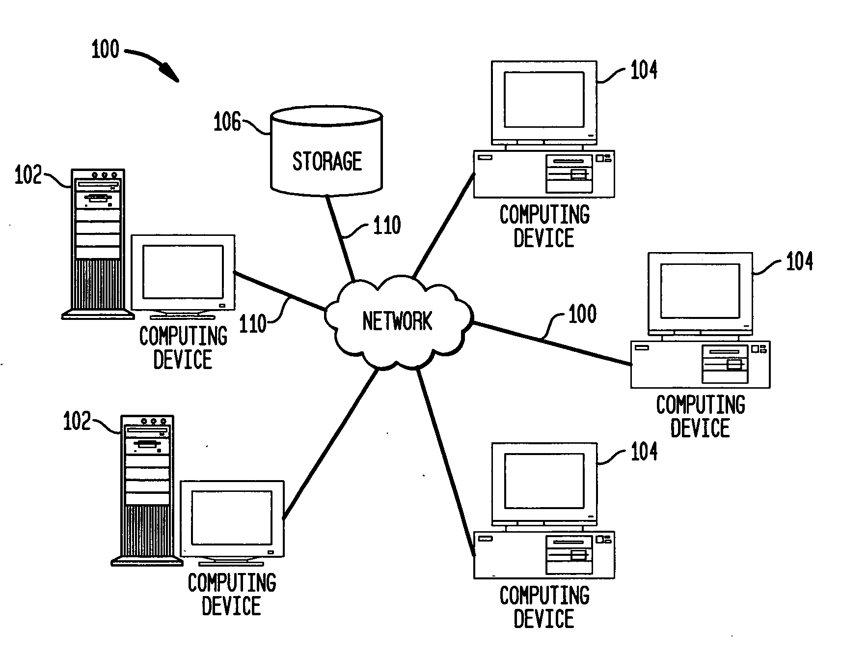
[0019]FIG. 1 illustrates a computer network 100, including servers 102, clients 104 and data storage unit 106. Network 100 also includes data connections 110 for transmitting data between the devices of the network. Network 100 may be, for example, the Internet, but could also be an intranet, a local area network, a wide area network, point-to-point links, or other networks.

[0020] Any suitable servers 102 may be used in the network 100. Also, the clients 104 of network 100 may be, for example, personal computers, laptop computers, servers, workstations, main frame computers, or other devices capable of communicating over the network. Similarly, connectors 110 may comprise a wide range of suitable devices, such as wire, fiber optics or wireless communication links.

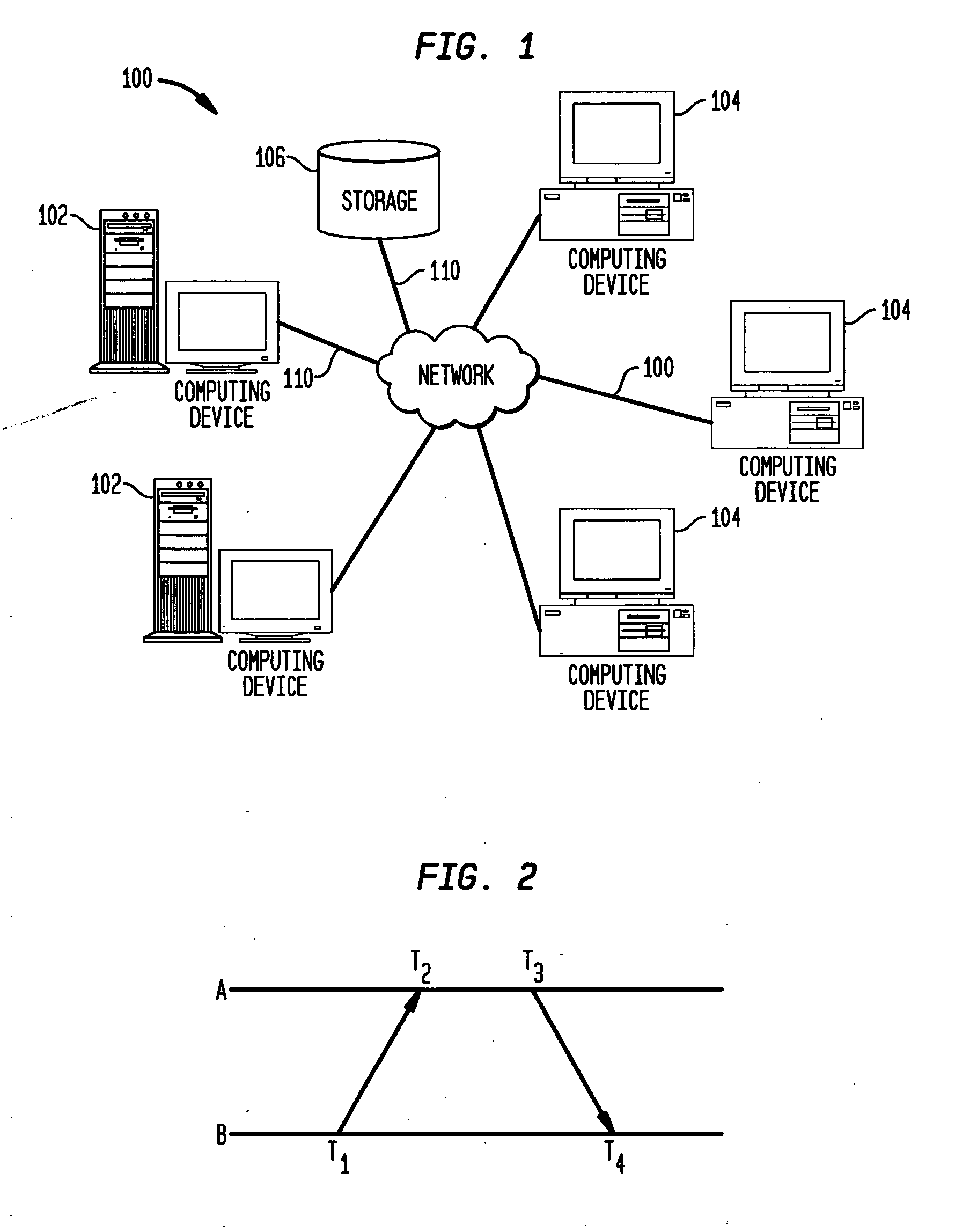
[0021] As mentioned above, various computer timing protocols, including the Server Timing Protocol (STP), require information about the skew and offset between two clocks in computer systems or networks, such as network 1...


PUM


Abstract

Disclosed are a method and system for estimating the skew and offset between two clocks in a computer system. The method comprises the steps of obtaining a first set of data values representing a forward delay between the first and second clocks, and obtaining a second set of data values representing a negative backward delay between the first and second clocks. The method comprises the further steps of forming a lower convex hull for said first set of data values, and forming an upper convex hull, above the lower convex hull, for said second set of data values. The clock offset and the skew between said first and second clocks are estimated using those convex hulls. In a preferred embodiment, this estimation is made by identifying a best clock line between the first and second convex hulls.

Description

CROSS REFERENCE TO RELATED APPLICATIONS [0001] This application is related to copending application no. (Attorney Docket POU920050125US1) for “Clock Filter Dispersion,” filed herewith; application no. (Attorney Docket POU(2005127US1) for “Use of T4 Timestamps To Calculate Clock Offset And Skew,” filed herewith; and application no. (Attorney Docket POU920050128US1), for “Filter Turning Point Detection,” filed herewith. The disclosures of the above-identified applications are herein incorporated by reference in their entireties. BACKGROUND OF THE INVENTION [0002] 1. Field of the Invention [0003] This invention generally relates to computer systems, and in particular to time synchronization in computer systems. Even more specifically, the invention relates to methods and systems for the estimation of clock offset and skew between two clocks in a computer system. [0004] 2. Background Art [0005] Modern computers use clocks for many purposes, including ensuring that many operations occur ...

Claims


Application Information

Patent Timeline
Patent Type & Authority Applications(United States)
IPC IPC(8): H04J3/06
CPCH04J3/0667
Inventor CARLSON, SCOTT M.THEODORE HACK, MICHEL HENRIZHANG, LI
Owner IBM CORP
Why Eureka
Try Eureka