Turbine fuel pump
a turbine fuel pump and turbine technology, applied in the direction of marine propulsion, vessel construction, other chemical processes, etc., can solve the problems of reduced pump efficiency, impeller torque loss, and torque loss, and achieve the effect of improving pump efficiency in the entire operating rang
- Summary
- Abstract
- Description
- Claims
- Application Information
AI Technical Summary
Benefits of technology
Problems solved by technology
Method used
Image

Examples
first embodiment
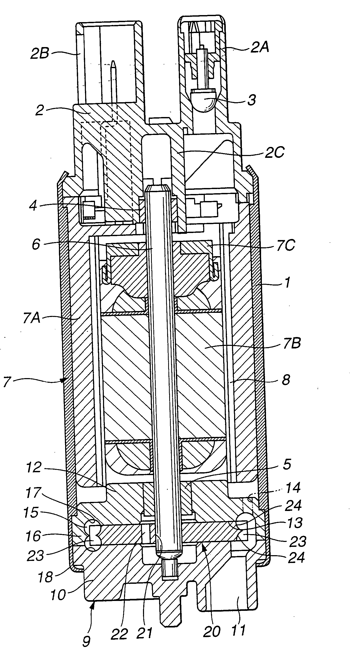
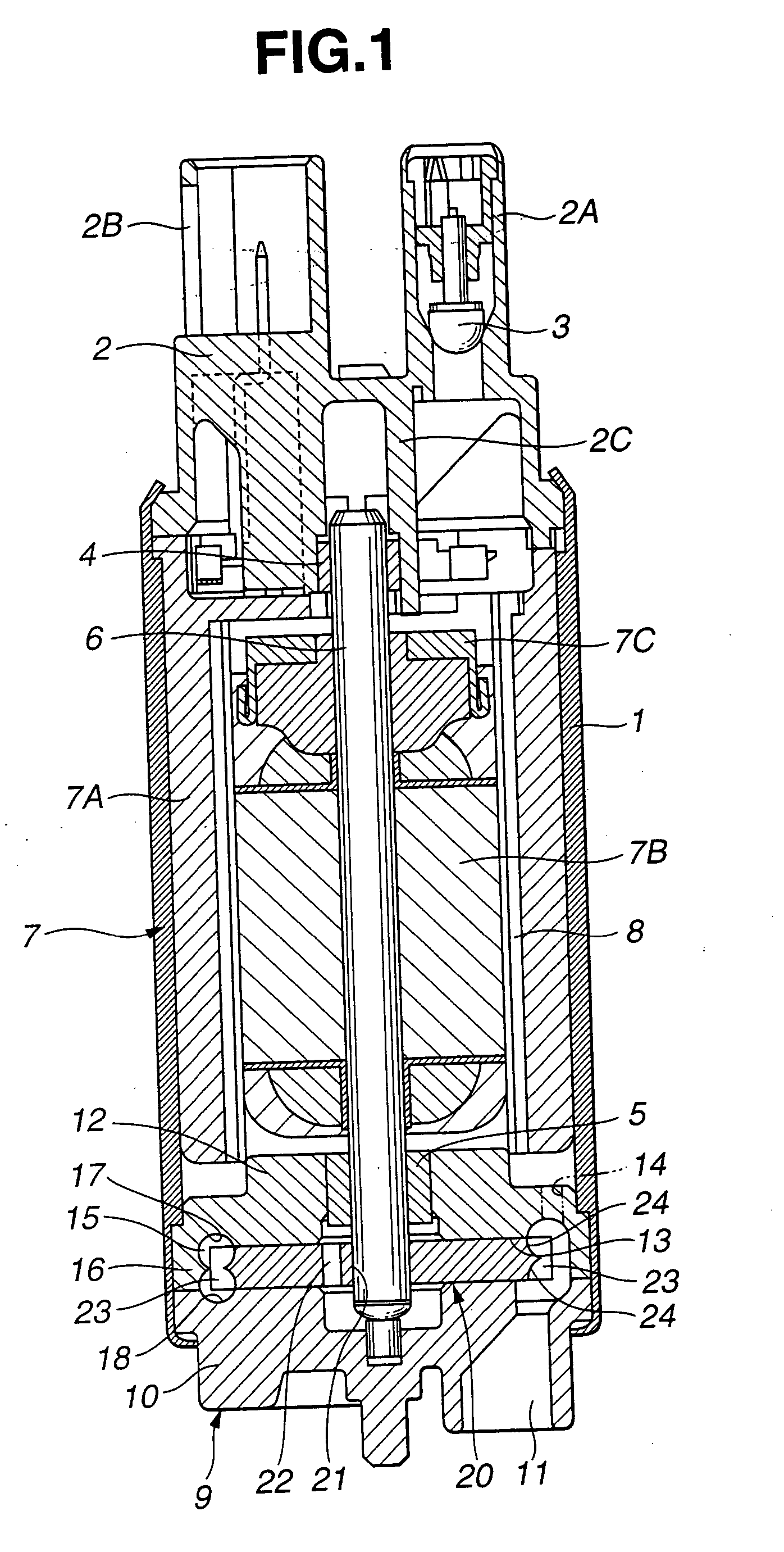
[0040] Referring to FIGS. 1-7, there is shown first embodiment of the present invention. Referring to FIG. 1, the turbine fuel pump comprises a cylindrical casing 1 which constitutes an outer shell of the pump and has axial ends closed by a delivery cover 2 and a pump housing 9.
[0041] The delivery cover 2 of a covered cylinder is arranged at one end of the casing 1. As shown in FIG. 1, the delivery cover 2 is provided with a delivery pipe 2A and a connector 2B which protrude upward and a bearing sleeve 2C arranged in the center to extend downward.
[0042] A check valve 3 is arranged in the delivery pipe 2A to hold the residual pressure. During rotation of an electric motor 7, the check valve 3 is opened by fuel flowing into the casing 1 to allow fuel to be delivered from the delivery pipe 2A to an outside fuel line (not shown). During halts of the electric motor 7, the check valve 3 is closed to prevent fuel within the fuel line from returning to the casing 1, thus holding the fuel l...
second embodiment
[0100] In the second embodiment, the chamfer 39 obtained by slantly cutting a comer between the side face 35C and the rear face 35B is arranged on the side of the impeller 32. Therefore, when rotating the impeller 32, the chamfer 39 allows smooth flow of fuel along the root-side chamfer portion 39A and the head-side chamfer portion 39B.
[0101] Moreover, the chamfer 39 is designed such that the ratio of the overall length T extending in the radial direction of the impeller 32 with respect to the radial length L of the fuel passage 31 is set at 9 / 20- 11 / 20(preferably, ⅖-⅗ (preferably, ½).
[0102] Thus, in the second embodiment, the position and length of the chamfer 39 (root-side chamfer portion 39A) and the angle of inclination of the root-side chamfer portion 39A can be set to correspond to the inflow position of fuel flowing into the blade grooves between the blades 35 through the fuel passage 31, the size required for smooth fuel inflow, and the angle allowing smooth fuel inflow, pr...
third embodiment
[0103] Referring to FIGS. 15-23, there is shown third embodiment of the present invention. Referring to FIG. 15, the turbine fuel pump comprises a cylindrical casing 101 which constitutes an outer shell of the pump and has axial ends closed by a delivery cover 102 and a pump housing 109.
[0104] The delivery cover 102 of a covered cylinder is arranged at one end of the casing 101. As shown in FIG. 15, the delivery cover 102 is provided with a delivery pipe 102A and a connector 102B which protrude upward and a bearing sleeve 102C arranged in the center to extend downward.
[0105] A check valve 103 is arranged in the delivery pipe 102A to hold the residual pressure. During rotation of an electric motor 107, the check valve 103 is opened by fuel flowing into the casing 101 to allow fuel to be delivered from the delivery pipe 102A to an outside fuel line (not shown). During halts of the electric motor 107, the check valve 103 is closed to prevent fuel within the fuel line from returning to...
PUM
 Abstract
Description
Claims
Application Information