Fuel cell system

a fuel cell and laser light technology, applied in the direction of lasers, optical resonator shape and construction, electrochemical generators, etc., can solve the problems of not always satisfying the stability of pulse output of laser light sources, the energy or power of output pulsed laser light sources, and the feedback control of laser light sources as disclosed, so as to achieve the effect of stabilizing the peak power or energy of output laser ligh

Inactive Publication Date: 2007-04-19
MEGAOPTO
View PDF5 Cites 6 Cited by
  • Summary
  • Abstract
  • Description
  • Claims
  • Application Information

AI Technical Summary

Benefits of technology

[0010] An object of the present invention is to provide a laser light source improved in stabilization of energy or power of output pulsed laser light.
[0016] The laser light source according to the embodiment is preferably arranged as follows: the control part performs control based on the power of the emitted light monitored by the monitor part at an end of a period in which the cavity loss is set at the first predetermined loss, thereby stabilizing the peak power or the energy of the output laser light. In this case, the peak power or the energy of the output laser light is further stabilized.

Problems solved by technology

However, the conventional laser light sources do not always achieve satisfactory stability of pulse output.
However, the laser light sources adapted for feedback control as disclosed in the above-described Documents 1, 2 were not always satisfactory in terms of the energy or power of the output pulsed laser light.

Method used


Image

  • Fuel cell system
  • Fuel cell system
  • Fuel cell system

Examples


first embodiment

[0027] (First Embodiment)

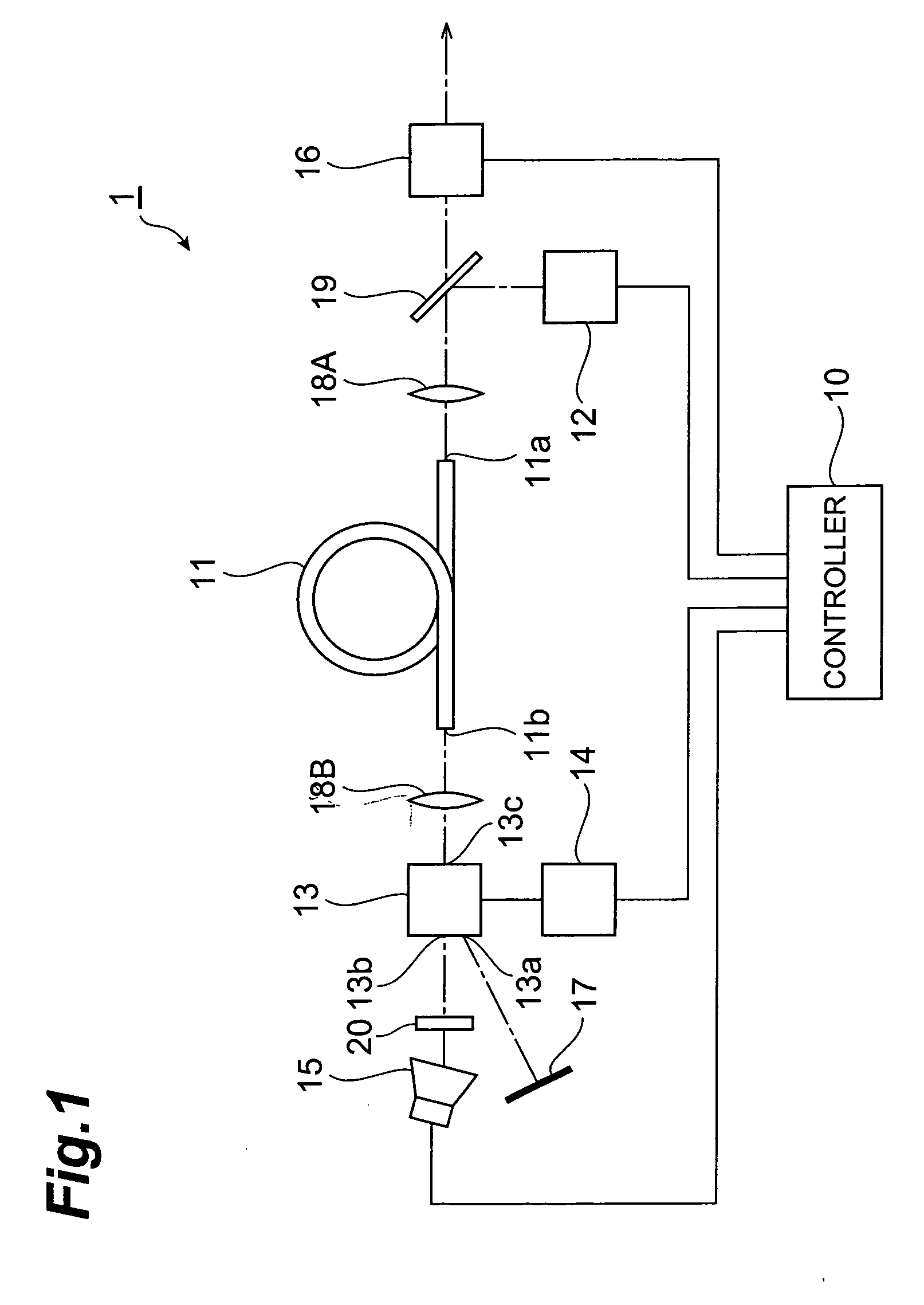
[0028] First, the first embodiment of the laser light source will be described. FIG. 1 is a configuration diagram of the laser light source 1 according to the first embodiment. The laser light source 1 shown in this figure is provided with a control part 10, an optical amplifying fiber 11, an excitation light source 12, an optical switch 13, a drive circuit 14, a monitor part 15, an output light power adjuster 16, a total reflection mirror 17, a lens 18A, a lens 18B, and a dichroic mirror 19.

[0029] The optical amplifying fiber 11 is an optical fiber in which an optical waveguide region is doped with a fluorescent element, and the fluorescent element emits fluorescence with supply of excitation light (pump light) of a wavelength capable of exciting the fluorescent element. This fluorescent element is preferably a rare-earth element, and among others, it is preferably Er, Yb, or the like. One end face 11aof the optical amplifying fiber 11 is a vertical cleava...

second embodiment

[0049] (Second Embodiment)

[0050] Next, the second embodiment of the laser light source according to the present invention will be described. FIG. 9 is a configuration diagram of the laser light source 2 according to the second embodiment. The laser light source 2 shown in this figure is provided with a control part 20, an optical amplifying fiber 21, an excitation light (pump light) source 22, an optical switch 23, a drive circuit 24, a monitor part 25, an output light power adjuster 26, an optical coupler 27A, an optical coupler 27B, and an optical isolator 28.

[0051] The optical amplifying fiber 21 is an optical fiber in which an optical waveguide region is doped with a fluorescent element, and the fluorescent element emits fluorescence with supply of excitation light of a wavelength capable of exciting the fluorescent element. This fluorescent element is preferably a rare-earth element, and among others, it is preferably Er, Yb, or the like. One end of the optical amplifying fibe...


PUM

PropertyMeasurementUnit
wavelength bandaaaaaaaaaa
diameteraaaaaaaaaa

Abstract

The present invention discloses a laser light source for implementing pulsed oscillation of laser light, which has a laser cavity in which a laser medium for generating emitted light with supply of excitation energy is placed on a resonance path; an excitation device for continuously supplying excitation energy to the laser medium; a monitor part for monitoring a power of light extracted at a middle point of the path of the cavity from the laser medium in accordance with the supply of the excitation energy by the excitation device; a Q-switch for modulating a cavity loss of the laser cavity; and a control part for performing such control as to stabilize a peak power or an energy of laser light pulses outputted in a state in which the cavity loss of the laser cavity is set at a second predetermined loss for oscillation of high-power pulses, based on the power of the emitted light monitored by the monitor part in a state in which the cavity loss of the laser cavity is set at a first predetermined loss for non-oscillation of high-power pulses.

Description

BACKGROUND OF THE INVENTION [0001] 1. Field of the Invention [0002] The present invention relates to a laser light source for implementing pulsed oscillation of laser light. [0003] 2. Related Background Art [0004] A laser light source for implementing pulsed oscillation of laser light is provided with a laser cavity in which a laser medium for generating emitted light with supply of excitation energy is placed on a resonance path, a Q-switch device for modulating a cavity loss of the laser cavity, and an excitation device for continuously supplying the excitation energy to the laser medium. [0005] This laser light source is configured as follows: while the cavity loss of the laser cavity is set at a large value by the Q-switch device, the population inversion of the laser medium is enhanced with supply of excitation energy by the excitation device; when the cavity loss of the laser cavity is then set to a smaller value by the Q-switch device, induced emission occurs in a short perio...

Claims


Application Information

Patent Timeline
Patent Type & Authority Applications(United States)
IPC IPC(8): H01M8/04
CPCH01M8/04186H01M8/04208H01M8/0687H01S3/067H01S3/06791H01S3/08H01S3/09415H01S3/1022H01S3/117H01S3/1306H01S3/1312H01S3/1618Y02E60/50H01M8/04
Inventor KAKUI, MOTOKI
Owner MEGAOPTO
Why Eureka
Try Eureka