Photoacoustic measurement of analyte concentration in the eye

a technology of analyte concentration and photoacoustic measurement, which is applied in the field of noninvasive in vivo, can solve the problems of inaccurate location and size of the absorbing tissue region, affecting the measurement of blood glucose levels, and all approaches suffer from a number of drawbacks

a technology of analyte concentration and photoacoustic measurement, which is applied in the field of noninvasive in vivo, can solve the problems of inaccurate location and size of the absorbing tissue region, affecting the measurement of blood glucose levels, and all approaches suffer from a number of drawbacks

US20070088206A1Inactive Publication Date: 2007-04-19MINU

Image

  • Photoacoustic measurement of analyte concentration in the eye
  • Photoacoustic measurement of analyte concentration in the eye

Examples


Embodiment Construction

[0024] In one embodiment of the inventive system, the glucose concentration is measured in the eye, by a photoacoustic assay such as that described in U.S. Pat. No. 6,846,288 (e.g. at Col. 13, line 62 to Col. 18, line 49) or in U.S. Pat. No. 6,403,904, each of which is incorporated by reference in their entirety.

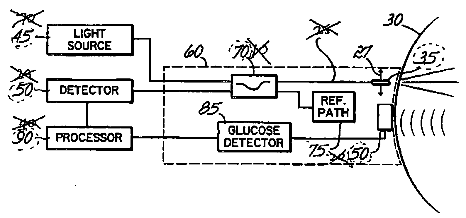
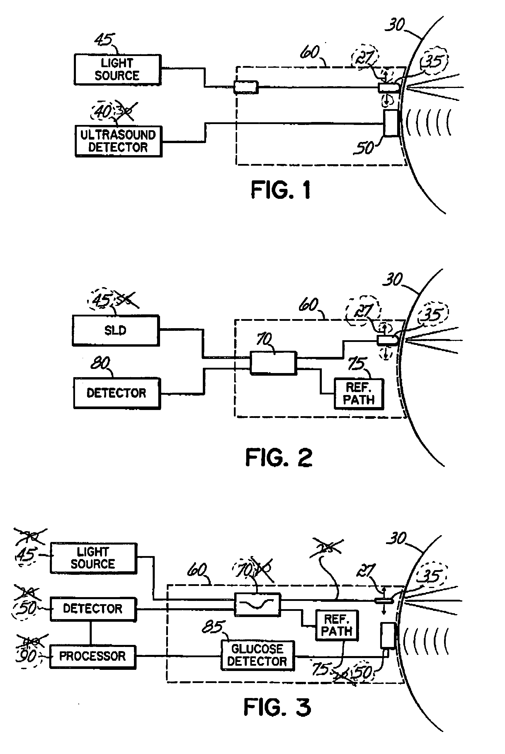
[0025] As shown in FIG. 1, the probe module 60 includes an objective lens structure 35, which is coupled to a light source 45 via a fiber optic connection or other light transmitter. Light source 45 provides light at a wavelength which is preferentially absorbed by glucose. Alternatively, the light source may be incorporated into the probe module 60.

[0026] The light source 45 may be a laser, laser diode or superluminescent diode (SLD), as appropriate for generating the desired light wavelength and intensity. The light may be delivered as pulses or as modulated radiation,

[0027] The probe module 60 further contains an ultrasound transducer 50 to detect the photoacoustic wav...


PUM


Abstract

In one aspect, the invention features a method and device for measuring blood concentration of a substance such as glucose in the aqueous humor by illuminating the aqueous humor with a light source at a frequency that is absorbed by the substance to the measured, and then sensing photoacoustically generated sound waves originated within the aqueous humor as a consequence of illumination by the light source. The blood concentration can be estimated from the amplitude of the sound waves received. The method may be combined with other optical techniques for glucose measurement and / or with optical or ultrasonic techniques for topographic mapping of eye structures.

Description

CROSS REFERENCE TO RELATED APPLICATIONS [0001] This application is a continuation of U.S. application Ser. No. 60 / 727,078, filed Oct. 14, 2005, which is hereby incorporated by reference herein in its entirety.FIELD OF THE INVENTION [0002] The invention relates to a non-invasive, in-vivo method and a system for the determination of the concentration of a substance in different areas of the eye. BACKGROUND OF THE INVENTION [0003] Many medical diagnostic techniques project radiant energy into the body of an animal for testing for the existence of a biomedical disorder or condition. For example, the integrity of the skeletal structure may be examined by passing X-rays through the body. The dense bony material substantially blocks the passage of the X-rays, permitting a doctor or other medical care provider to visually inspect for fractures or other defects in the skeletal structure. [0004] To examine the soft tissue of the body, other techniques are available. These include, among other...

Claims


Application Information

Patent Timeline
19 Apr 2007
Publication
US20070088206A1
IPC
A61B5/00
CPC
A61B5/14532; A61B5/1455; A61B5/0095
Inventors
PEYMAN, GHOLAM A.; YONEYA, SHIN