Fluid transfer device

a technology of fluid transfer device and spherical fluid, which is applied in the direction of packaging foodstuffs, packaging goods types, applications, etc., to achieve the effect of being ready to break o

Inactive Publication Date: 2007-04-19
MEDIMOP MEDICAL PROJECTS
View PDF99 Cites 143 Cited by
  • Summary
  • Abstract
  • Description
  • Claims
  • Application Information

AI Technical Summary

Benefits of technology

[0012] The adaptor can be integrally formed with the flow control member and designed so as to readily broken off therefrom after rotation of the flow control member from its first flow control position to its second flow control position. Alternatively, the adaptor can be detachably engaged to the flow control member by means of an interengaging means enabling axial detachment of the adaptor from the body member on a relative rotation therebetween to a position which urges the flow control member from its first flow control position to its second flow control position.

Problems solved by technology

The problem of ensuring proper fluid transfer under aseptic conditions is especially acute in the case of Self-administration of drugs by patients in their homes.

Method used


Image

  • Fluid transfer device
  • Fluid transfer device
  • Fluid transfer device

Examples


first embodiment

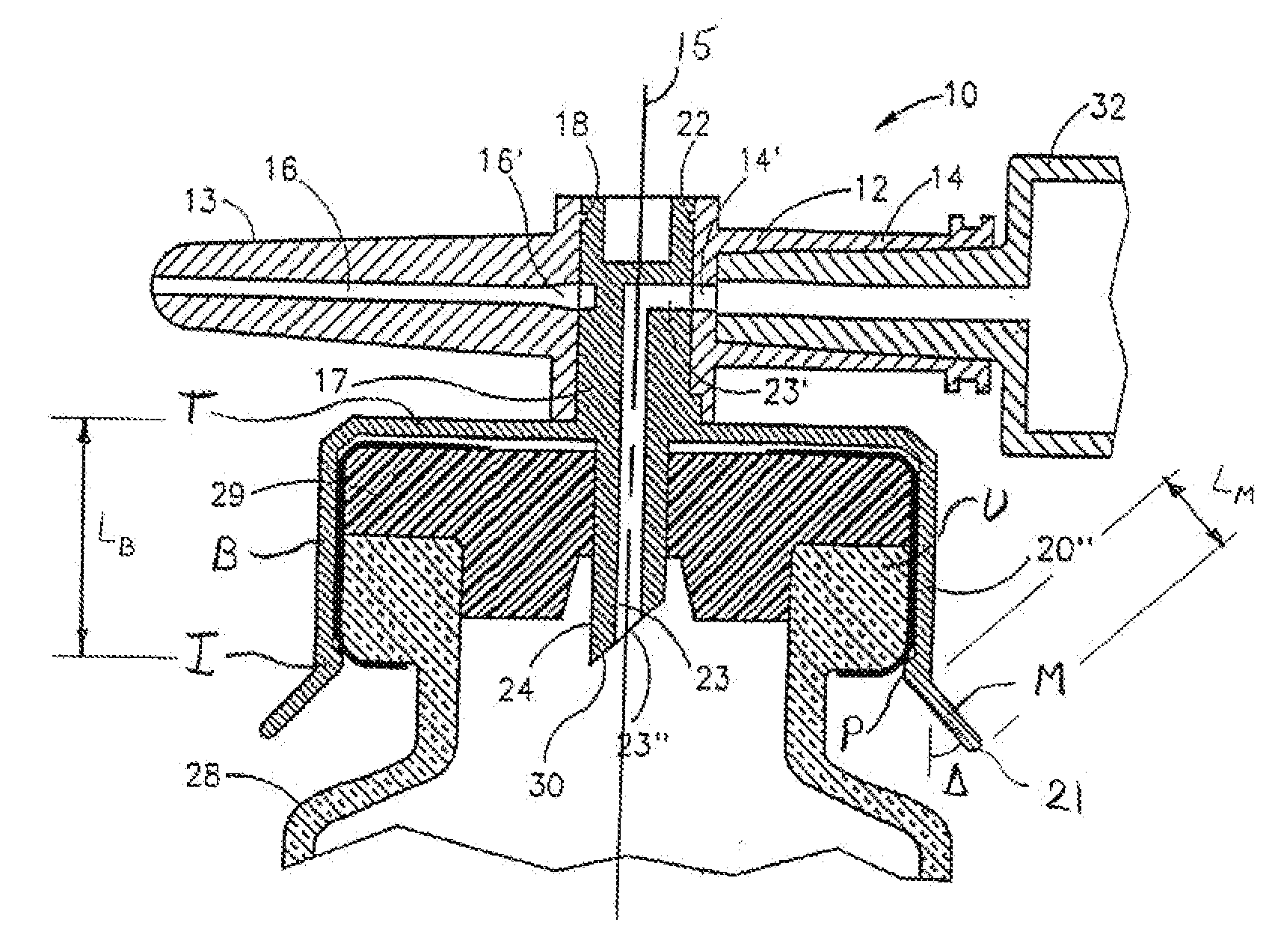
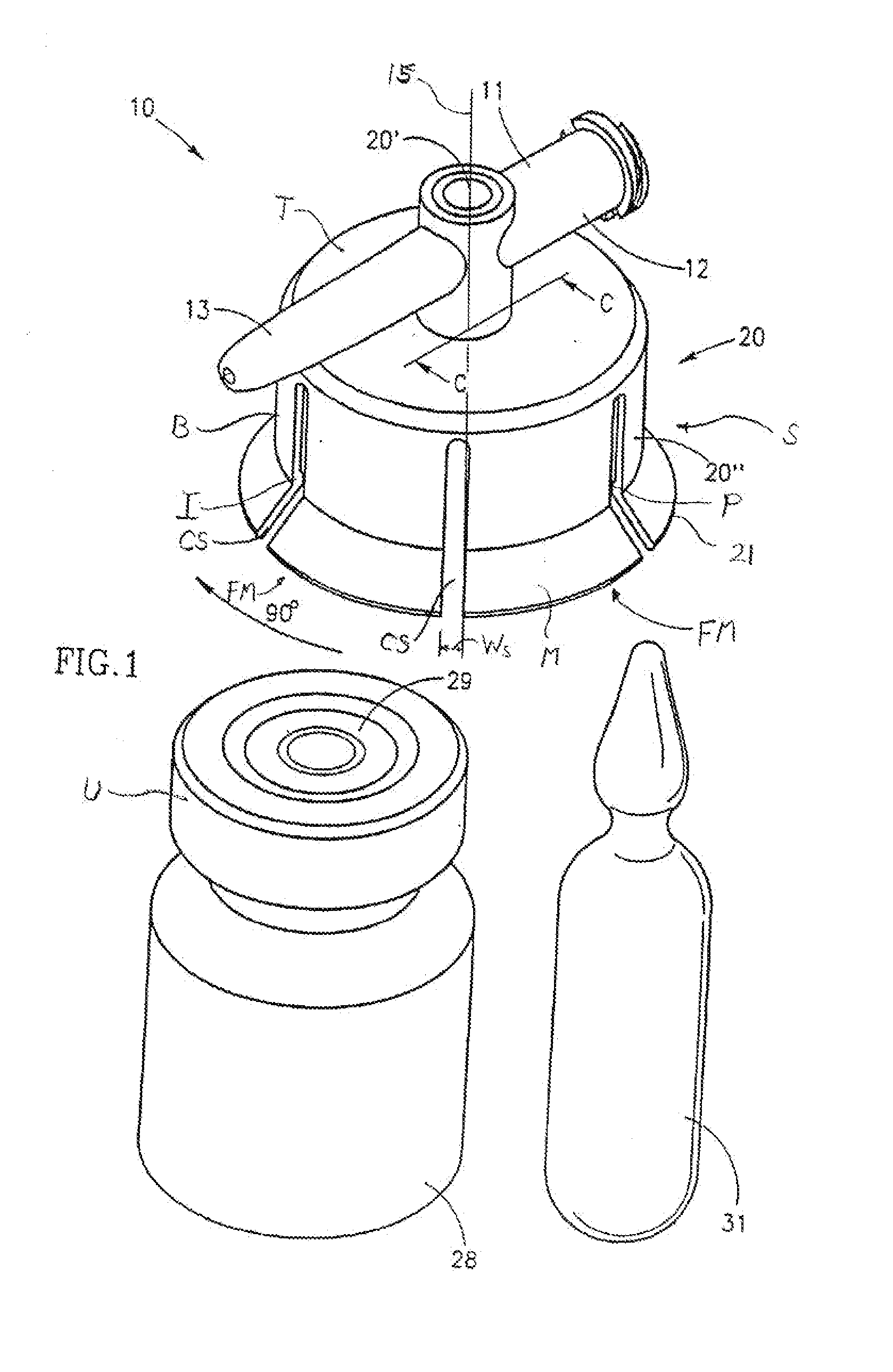
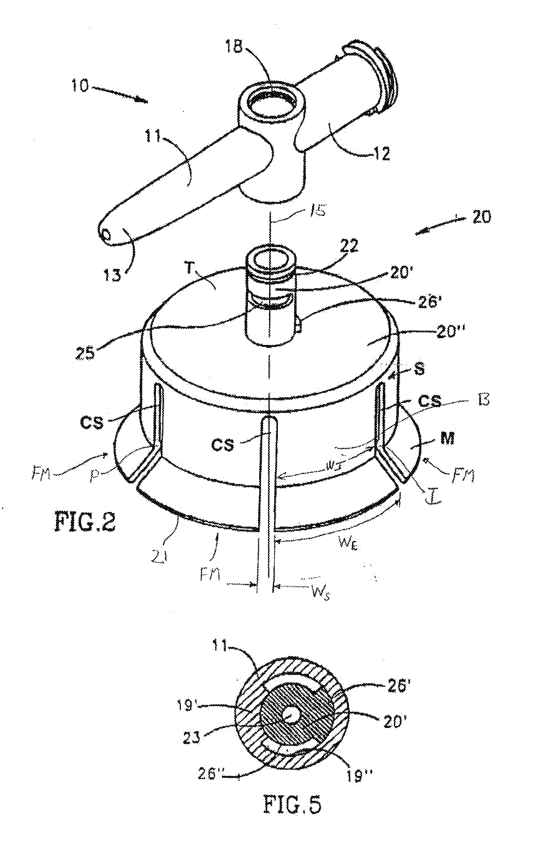
[0055]FIGS. 1-8 depict a fluid control or fluid transfer device, generally designated 10, constructed and operative in accordance with the teachings of the present invention for enabling fluid flow control between a syringe 32, a medicinal vessel 28 and a dispensing port 13. The fluid transfer device 10 includes an elongated base member 11 having a port 12 adapted for receiving a syringe 32 and a dispensing port 13 fashioned as a plastic cannula for insertion into a pre-slit septum assembly known in the art per se. The port 12 is typically fashioned as a female Luer connector 12. The fluid transfer device 10 includes a longitudinal axis 15. As is understood by one having ordinary skill in the art, a fluid transfer device typically include a lumen connecting two port, while a fluid control device typically includes a flow control member for diverting flow between at least two flow paths, however, these terms are not meant to be limiting.

[0056] As shown in FIG. 3, the port 12 includes...

second embodiment

[0065]FIGS. 9 and 10 depict a fluid control or transfer device, generally designated 34, constructed and operative in accordance with the teachings of the present invention for enabling fluid flow control between a syringe, a medicinal vessel and a dispensing port. The fluid control device 34 is similar in construction and operation to the fluid control device 10 and therefore the same reference numbers are used where appropriate.

[0066] The main difference between the two fluid control devices 34 and 10 resides in the fact that the former includes an integrally formed adaptor cum flow control member 35 provided with a weakened portion, generally designated 36, between its abutment wall portion 26′ of its flow control member 35′ and its adaptor 35″. As shown, this weakened portion 36 is achieved by leaving radially extending vanes 36′ formed by cut-outs 36″.

[0067] The advantage of this design is that after rotation of the vial 28 (not shown) and the adaptor 35″ through ninety degree...

third embodiment

[0069]FIGS. 13-15 depict a fluid control device, generally designated 40, constructed and operative in accordance with the teachings of the present invention for enabling fluid flow control between a syringe, a medicinal vessel and a dispensing port. The fluid control device 40 is similar in construction and operation to the fluid control device 10 and therefore the same reference numerals are used where appropriate.

[0070] The main difference between the two fluid control devices 10, 40 is that the former includes an adaptor 41 designed for a non-destructive detachable engagement with a flow control member 42. As such, the base member 11 is provided with a downwardly depending rectangular shaped skirt 43 provided with outwardly extending flanges 43′, 43″ for engagement by an upwardly extending rectangular shaped grip 44 of the adaptor 41 provided with inwardly directed grooves 44′, 44″ for receiving the flanges 43′, 43″. In addition, the adaptor 41 is provided with an upwardly exten...


PUM


Abstract

A fluid ducting assembly for enabling flow communication between a syringe and either one of a vessel and a dispenser for dispensing a fluid contained, a priori in the syringe or in the vessel. The fluid ducting assembly includes a base having a first member, a second member, and a third member for connection to and providing flow communication with the syringe, the vessel and the dispenser, respectively. The fluid ducting assembly further includes a flow controller within the base enabling any one of a flow path between the first member and the second member and a flow path between the first member and the third member. The flow controller has either a first operative position in which the flow path between the first member and the second member in enabled or a second operative position in which the flow path between the first member and the third member is enabled. The flow controller being readily switchable from its first operative position to its second operative position but not readily switchable form its second operative position to its first operative position.

Description

CROSS-REFERENCE TO RELATED APPLICATIONS [0001] This patent application is a continuation of U.S. patent application Ser. No. 10 / 062,796, filed Jan. 31, 2002 which is a continuation-in-part of U.S. patent application No. 09 / 633,056, now U.S. Pat. No. 6,379,340 B1 filed Aug. 8, 2000, which is a divisional of U.S. patent application Ser. No. 08 / 913,432, now U.S. Pat. No. 6,238,372 B1, filed Sep. 17, 1997, which is a 371 National Phase application based on International Application No. PCT / US96 / 03732, which claims priority, to) U.S. patent application Ser. No. 08 / 499,213, filed Jul. 17, 1995, now abandoned, and U.S. patent application Ser. No. 08 / 407,257, filed Mar. 20, 1995, now abandoned.BACKGROUND OF THE INVENTION [0002] Drugs intended for parenteral administration are typically stored in a medicinal vessel either as a dry powder or as a solution. The solution can be ready for immediate use or in the form of a liquid concentrate which requires reconstitution with a physiological solu...

Claims


Application Information

Patent Timeline
Patent Type & Authority Applications(United States)
IPC IPC(8): A61B19/00A61J1/00A61J3/00A61J1/20A61M39/00A61M39/22
CPCA61J1/2089A61J1/2096A61J2001/201A61J2001/2013A61J2001/2058A61J2001/2062A61J2001/2075A61J2001/2082A61M5/162A61M39/18A61M39/223A61M2039/1077A61J1/201A61J1/2075A61J1/2062A61J1/2082A61J1/2013A61J1/2058
Inventor ZINGER, FREDDYDENENBURG, IGOR
Owner MEDIMOP MEDICAL PROJECTS
Why Eureka
Try Eureka