
Programmable automotive computer method and apparatus with accelerometer input

a computer method and input technology, applied in the field of vehicle computer devices and methods, can solve the problems of difficult installation, high cost of accessory gauges to display these operating conditions, and inability to accurately and reliably correct for velocity data errors, etc., to achieve accurate and reliable velocity data correction, easy data entry, and accurate detection of the start time

Active Publication Date: 2007-04-19
HYPERTECH
View PDF25 Cites 63 Cited by
  • Summary
  • Abstract
  • Description
  • Claims
  • Application Information

AI Technical Summary

Benefits of technology

[0025] An advantage of the present invention is that of using the combination of accelerometer data and PID-based velocity data in a way that delivers accuracy not possible with either of these two systems alone.
[0026] An advantage of the present invention is that it provides for accurate detection of the start time of first movement of the vehicle independent of the onboard diagnostic system and its diagnostics port. According to a related advantage, the present invention determines the precise time taken to reach the first PCM delivered velocity value from the onboard diagnostics system.
[0027] Still another advantage of the present invention is that it accurately and reliably corrects for errors in velocity data from the onboard diagnostic system when a vehicle is exhibiting wheel spin.
[0028] Another advantage of the present invention is that it provides a touch screen user interface including an easy-to-use menu interface, a typewriter-style keyboard enabling easy data entry, and contextual help screens to facilitate use and eliminate the need for a separate user manual.
[0029] An advantage of the present invention is that it enables performance tuning by a user. The present invention enables a user to unlock the performance potential of computer-controlled vehicle engines by providing optimized fuel and ignition curves for enabling improved engine performance over the entire revolutions per minute (RPM) range. The present invention also gives a performance enthusiast and other users the ability to reprogram and personalize the onboard computer that controls virtually all aspects of the vehicle's operation. For example, the system enables adjustment of the engine RPM limiter for faster acceleration and adjustment of the top speed limiter for matching the speed rating of factory-approved tires. According to another aspect, the system enables correction of speedometer / odometer readings for non-stock tire sizes and gear ratios. The present invention, according to another aspect, enables a user to change the automatic transmission shift points and shift firmness to improve performance and enables adjustment of the on-off temperature of the vehicle's electric cooling fan. The present invention enables storage of the stock tuning calibrations in the memory of the device so that these calibrations can be selectively restored by a user.
[0030] Another advantage of the present invention is that it provides a drag strip function, i.e., a virtual drag strip, for accurately recording acceleration data, i.e., elapsed times and speeds, during a test run and presentation of the results of the test run to a user in a time slip format. The present invention, according to other aspects, also records and displays reaction time, incremental elapsed times and speed over several distances, time to speeds, e.g., 0-60 mph, 0-100 mph, and time to maximum speed. The present invention provides the vehicle performance information without the cost and inconvenience of using complex and expensive track testing equipment at a commercial drag strip.

Problems solved by technology

Conventionally, the monitoring and troubleshooting of identified faults required the use of bulky, complex equipment that was available only at automobile repair establishments.
The cost of accessory gauges to display these operating conditions, however, are often cost prohibitive and difficult to install.
A drawback of such devices is that the accelerometer requires very careful installation.
A key drawback of these accelerometer-based devices is the requirement of precise alignment with the vehicle's x, y, and z axes of movement, and especially the longitudinal axis, e.g., the straight line direction down a drag strip track.
The requirements for precise alignment with respect to these three axes are virtually impossible for known accelerometer-based devices to meet.
As a result, errors in the outputs generated by such devices are inherent and unavoidable.
Moreover, any misalignments of the accelerometer causes errors in the vector pointing down the track which results in a continuously increasing error in the velocity values, the first integral of the accelerations.
This error for accelerometer-based devices is further compounded in the distance calculations, the second integral of the accelerations.
Accelerometer-based devices are also subject to errors due to “bouncing” and “tilting” during acceleration of the vehicle.
For example, the lifting of the vehicle's front end and the dropping down of the rear end exhibited during acceleration both affect the vector for straight line acceleration, thereby causing both random and systematic errors.
For all of the above reasons, known accelerometer-based devices have the drawback of being subject to error.
Two of the drawbacks of known PID-based devices are that the initial starting point and starting time are unknown.
As a result, there is an unknown error such that any previous attempts at using PCM velocity values provided at the diagnostic port to generate distance traveled and acceleration tests have always contained an error that varies from test to test randomly, and, therefore, gives false, unreliable fluctuating results.
In addition to not knowing the precise starting point on the track for a test, the initial time “zero” of the test, i.e., the moment in time of first movement by the vehicle, is also an unknown for conventional PID-based devices.
Wheel spin presents another challenge because the velocity values from the diagnostic port are distorted during the time the vehicle's wheels are spinning, such that distance calculations would otherwise be inaccurate.
As a result, the integral of the velocity curves is exaggerated and all distances and time-to-distance calculations are incorrect and in proportion to the falsely-reported excess speed during the wheel spin.
Known PID-based devices do not accurately account for this wheel spin error.

Method used


Image

  • Programmable automotive computer method and apparatus with accelerometer input
  • Programmable automotive computer method and apparatus with accelerometer input
  • Programmable automotive computer method and apparatus with accelerometer input

Examples


Embodiment Construction

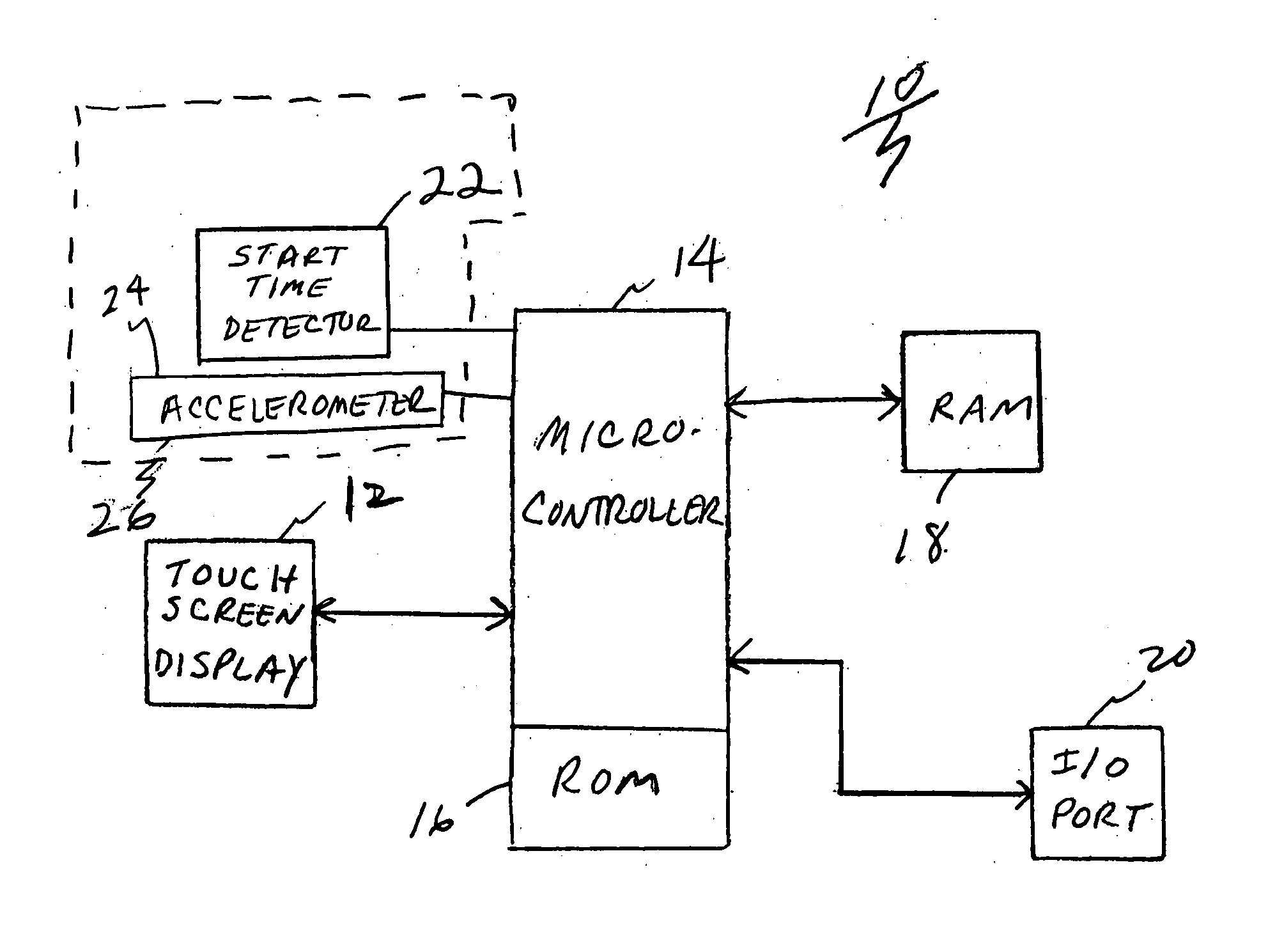
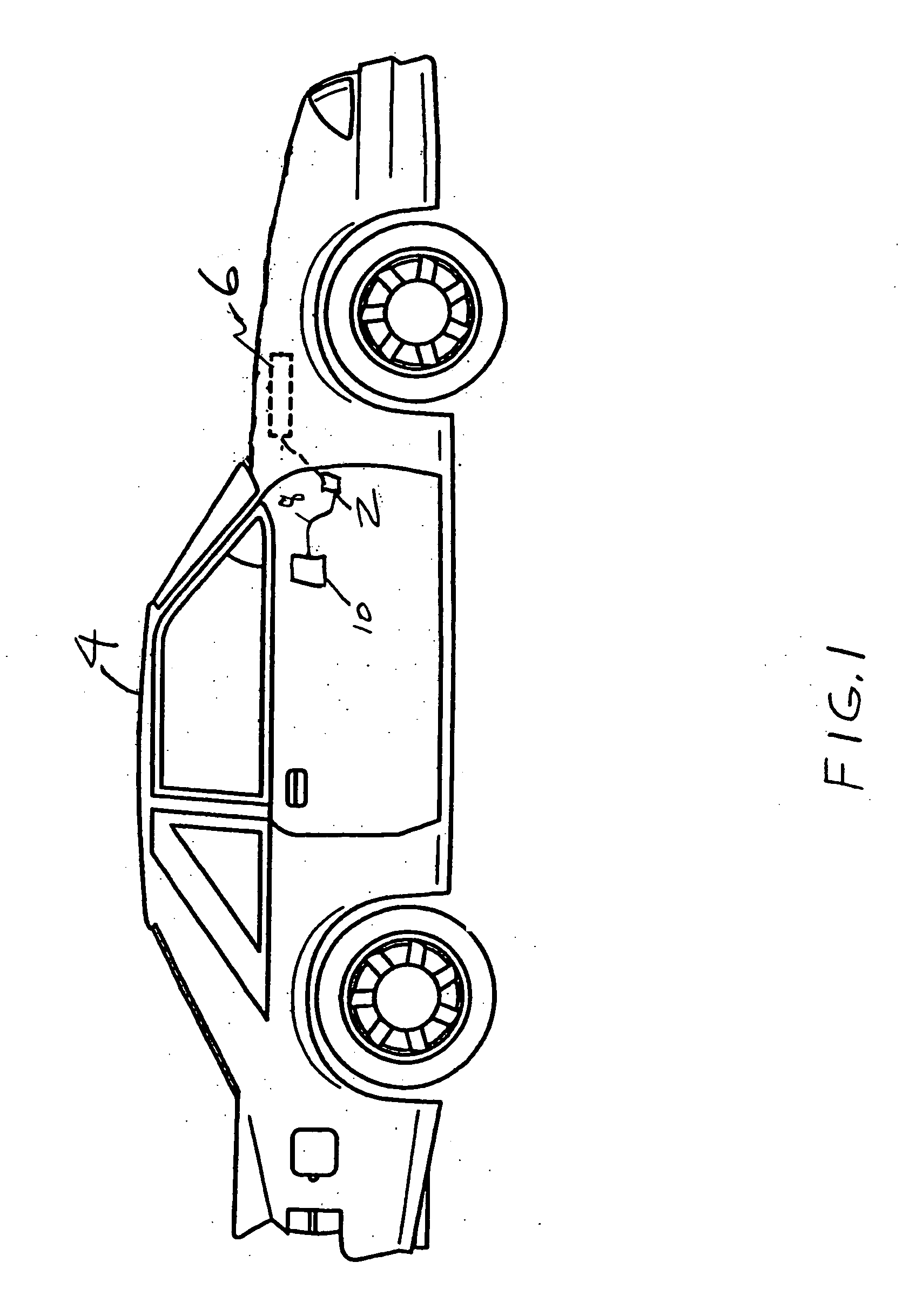
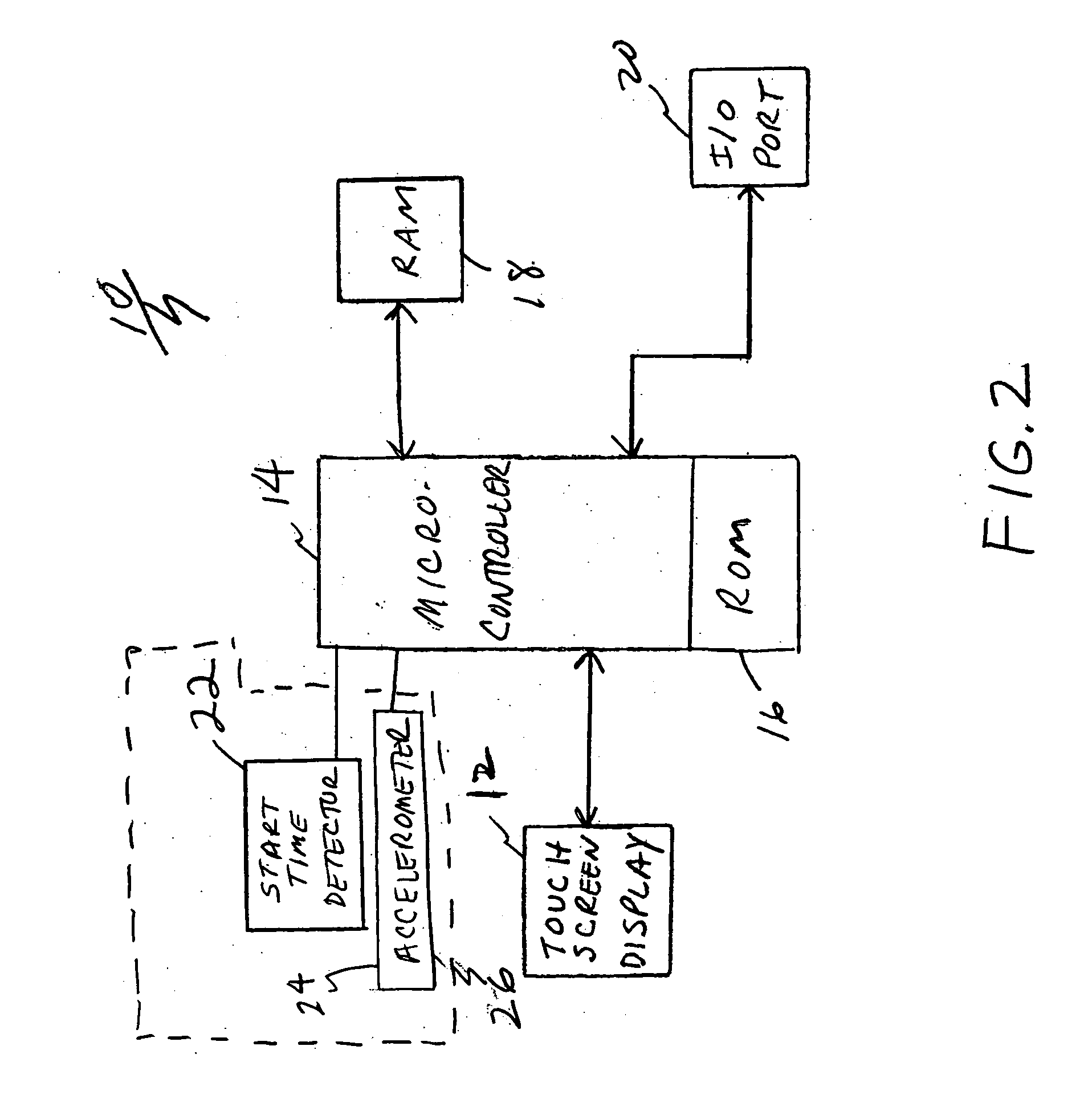
[0116] The device of the present invention is a portable programmable automotive computer. FIG. 1 is an illustration of an automobile 4 having an automotive computer 6, also referred to herein as a Powertrain Control Module or PCM, for controlling the operation thereof. Automotive computer 6 is coupled to an onboard diagnostic port 2, e.g., an OBD II port, accessible from the interior compartment of the automobile 4 as shown. Although automobile 4 is shown as a car, the present invention is also for use for other motor vehicles including trucks, sports utility vehicles (SUVs), hot rods, and the like. The diagnostic port 2 provides access to the PCM and provides engine characteristics and diagnostic codes information. A portable programmable automotive computer device 10 according to the present invention is coupled to diagnostic port 2. The programmable automotive computer device 10 is preferably coupled to the diagnostic port 2 via a cable 8 as shown in the embodiment in FIG. 1. It...


PUM


Abstract

A device and corresponding method for enabling a user to accurately control, monitor, and evaluate performance of a vehicle. A portable programmable computer device that a user can readily plug into a diagnostic connector port of the vehicle for providing the controlling, monitoring, and evaluating functions. Accurate detection of the start time of first movement of the vehicle is made based on data from an accelerometer, independent of the onboard diagnostic system and its diagnostics port. A clock is started for measuring time such that the precise time taken to reach the time-stamped first velocity value from the engine computer via the diagnostic port is determined. Data from the accelerometer and diagnostic port is analyzed and selectively used for accurately and reliably correcting for errors in velocity data from the onboard diagnostic system including latency error and errors due to the vehicle exhibiting wheel spin.

Description

CROSS REFERENCE TO RELATED APPLICATION [0001] This application claims the benefit of U.S. Provisional Application No. 60 / 732,579, filed Nov. 1, 2005, and this application is a continuation-in-part of prior Application Ser. No. 11 / 265,707, filed Nov. 1, 2005 which claims the benefit of U.S. Provisional Application No. 60 / 624,210, filed Nov. 1, 2004, all three applications are herein incorporated by reference.FIELD OF THE INVENTION [0002] The invention relates in general to vehicle computer devices and methods, and more particularly to a device, and corresponding method for enabling a vehicle operator to control, monitor, and evaluate vehicle performance. BACKGROUND OF THE INVENTION [0003] A typical automobile includes a myriad of sensors mounted around the engine and other vehicle modules for monitoring the condition and selected performance characteristics of the vehicle such as air intake, temperature, and the position and rate of change of the accelerator, etc. Typically, an engin...

Claims


Application Information

Patent Timeline
IPC IPC(8): G06F17/00
CPCG07C5/008G07C5/085
Inventor HEFFINGTON, MARK F.
Owner HYPERTECH
Learn More