
Gas turbine engine system and method of operating the same

a gas turbine engine and gas turbine engine technology, applied in the direction of machines/engines, turbine/propulsion fuel heating, mechanical equipment, etc., can solve the problems of high cost factors, reduced gas turbine performance, and high cost factors, and achieve the effect of improving system and method

Inactive Publication Date: 2007-04-26
GENERAL ELECTRIC CO
View PDF9 Cites 44 Cited by
  • Summary
  • Abstract
  • Description
  • Claims
  • Application Information

AI Technical Summary

Benefits of technology

[0005] Therefore, there is a need for an enhanced system and method

Problems solved by technology

During warm days, the gas turbine's performance may be reduced due to elevated air temperature at an inlet of the compressor.
However, open rack vaporizers and submerged combustion vaporizers have drawbacks, such as high cost factors, detrimental environmental impact, or the like.

Method used


Image

  • Gas turbine engine system and method of operating the same
  • Gas turbine engine system and method of operating the same
  • Gas turbine engine system and method of operating the same

Examples


Embodiment Construction

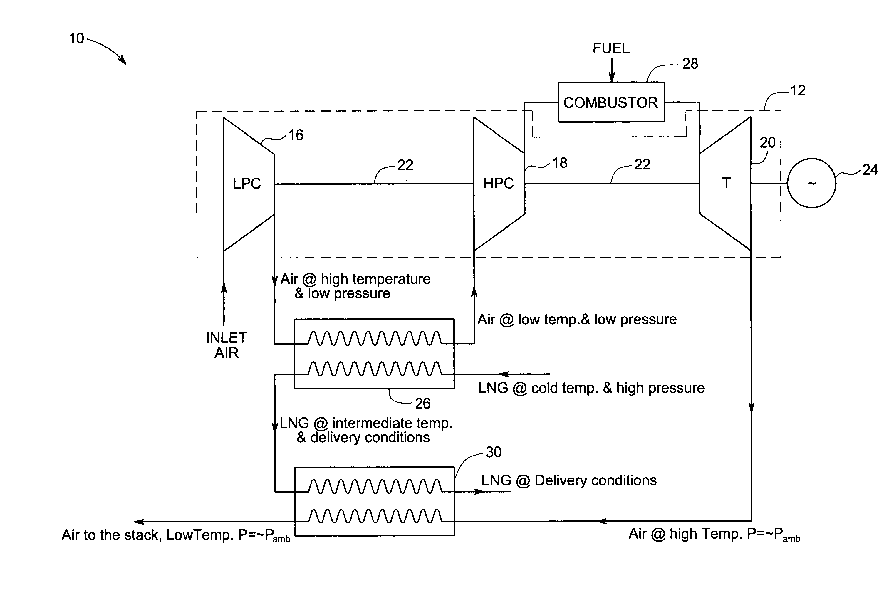
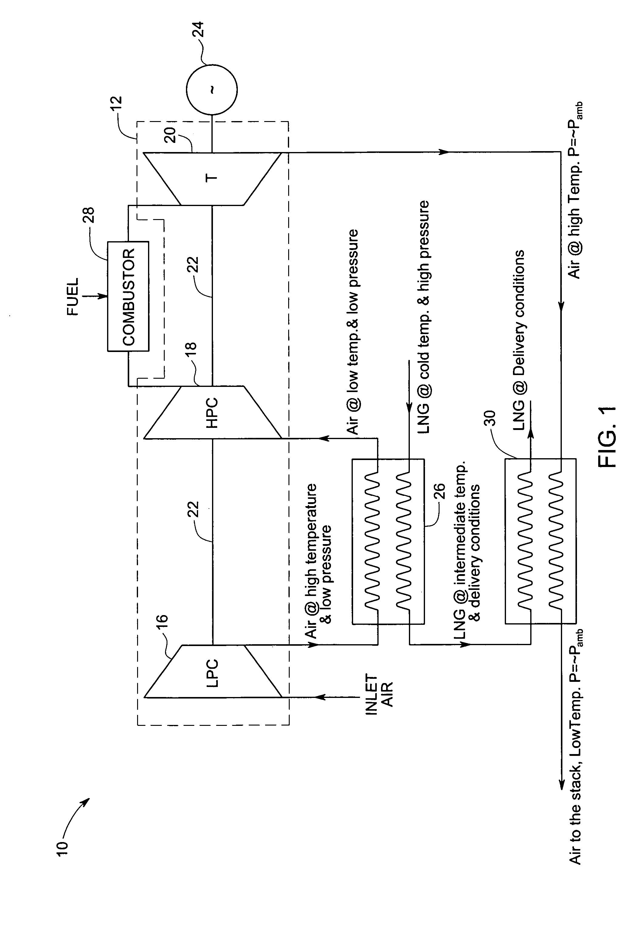
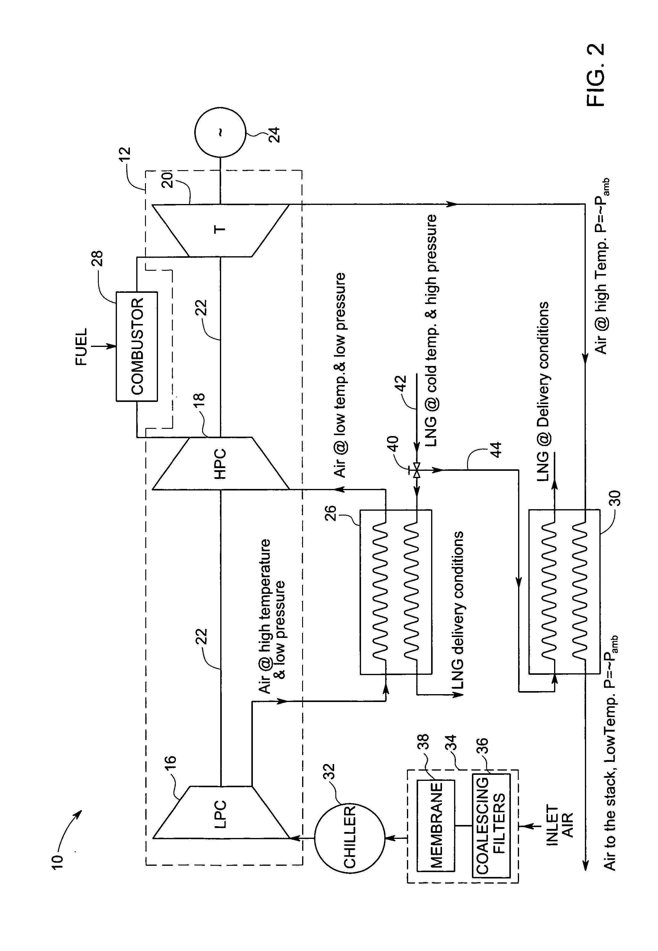
[0014] As discussed in detail below, embodiments of the present invention provide a gas turbine engine system, in which inlet air is compressed to higher pressures before being combusted with a fuel (for example, natural gas). Combustion products at high pressure and temperature are expanded through a turbine to generate power. Due to thermodynamic and gas dynamics considerations, combustion exhaust gases exit the turbine at relatively high temperature. The gas turbine engine system, in accordance with the aspects of the present invention, facilitates chilling of inlet air before compression, inter-cooling the air between compressor stages, and recover waste heat of the exhaust gas exiting the turbine. Liquid natural gas or a cooled intermediate working fluid is used as a coolant to extract heat. In certain exemplary embodiments, techniques in accordance with aspects of the present invention are disclosed in which liquid natural gas or the cooled intermediate working fluid is used f...


PUM


Abstract

A gas turbine engine system includes an intercooler coupled between a low-pressure compressor and a high-pressure compressor and configured to cool the compressed air exiting the low-pressure compressor. Liquid natural gas or a cooled intermediate working fluid is used in the intercooler to cool the compressed air exiting the low-pressure compressor. A mixture of fuel and compressed air from the high-pressure are combusted in a combustion chamber of an engine. A turbine is coupled to the engine and configured to expand combustion exhaust gas ejected from the engine to generate power. A heat exchanger is coupled to the turbine and the intercooler and configured to re-gasify the liquid natural gas. The exhaust air exiting the turbine or a heated intermediate working fluid is used to gasify the liquid natural gas in the heat exchanger.

Description

CROSS REFERENCE TO RELATED APPLICATIONS [0001] This application claims the benefit of U.S. Provisional Application No. 60 / 729,519 filed on Oct. 24, 2005, which is incorporated herein in its entirety by reference.BACKGROUND [0002] The present invention, in accordance with certain exemplary embodiments, relates generally to gas turbine engine systems and methods of operating a gas turbine engine system. As particular examples, the present invention provides a system and method for cooling compressed air using liquid natural gas and re-gasifying the liquid natural gas. [0003] Generally, in a gas turbine engine system, air is compressed in a compressor or a multi-stage compressor. Compressed air is mixed with fuel such as propane, natural gas, kerosene, jet fuel, or the like and combusted in a combustion chamber. Exhaust gas generated due to combustion is used to drive a turbine, which may be used to generate power or effectuate rotation. During warm days, the gas turbine's performance ...

Claims


Application Information

Patent Timeline
IPC IPC(8): F02C7/12
CPCF02C7/143F02C7/224
Inventor NORMAN, BRUCE GORDONALI, MOHAMED AHMEDJOSHI, NARENDRA DIGAMBERMOHAMED, SHERIF HATEM ABDULLA
Owner GENERAL ELECTRIC CO
Learn More