Pressure sensor device

Inactive Publication Date: 2007-04-26
KYOCERA CORP
View PDF8 Cites 51 Cited by
  • Summary
  • Abstract
  • Description
  • Claims
  • Application Information

AI Technical Summary

Benefits of technology

[0046] Furthermore in the pressure sensor device of the invention, the antenna pattern is meandered. Thereby,

Problems solved by technology

However, in the above-described conventional pressure sensor device, the surface acoustic wave element 104 formed on the sensor substrate 101 is exposed to the surface of the sensor substrate 101, and no member is provided to protect this, so that when this pressure sensor device is used in a manner in that pressure is applied to the sensor substrate 101, the surface acoustic wave element 104 is exposed to the air containing moisture, and this causes oxidation corrosion and deterioration of the surface acoustic wave element 104 made of aluminum or the like.
In such a case, it may become impossible to normally work the pressure sensor device.
In this case, the electrode fingers of the surface acoustic wave eleme

Method used


Image

  • Pressure sensor device
  • Pressure sensor device
  • Pressure sensor device

Examples


first embodiment

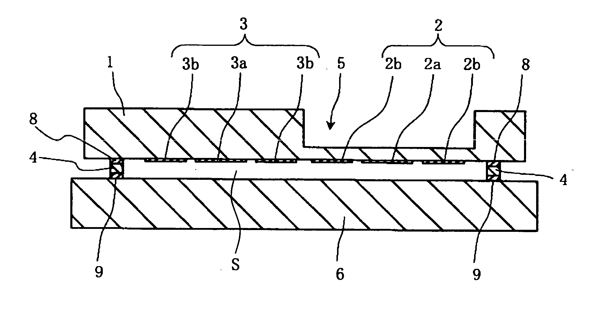
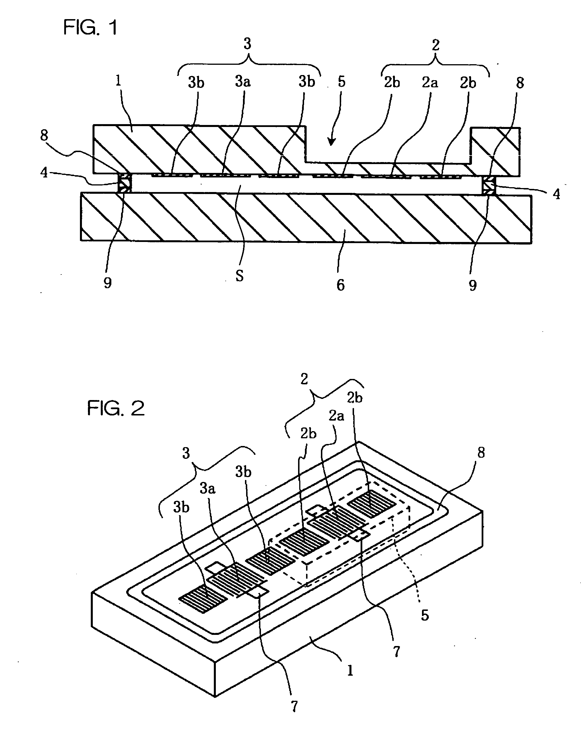
[0094]FIG. 1 is a sectional view of a pressure sensor device according to an embodiment of the invention, and FIG. 2 is a perspective view of surface acoustic wave elements 2 and 3 formed on the lower surface of a piezoelectric substrate 1 of the pressure sensor device.

[0095] The pressure sensor device is mainly constructed of a sensor substrate 1 on which is mounted a surface acoustic wave element 3 for reference and a surface acoustic wave element 2 for detecting pressure, a sealing member 4, and a supporting substrate 6.

[0096] A sensor section 11 is formed by the surface acoustic wave element 3 for reference and the surface acoustic wave element 2 for detecting pressure.

[0097] The sensor substrate 1 has in its upper surface a concave portion 5, and on the lower surface of the sensor substrate 1, the surface acoustic wave element 2 for detecting pressure is provided in a region immediately below the concave portion 5 (hereinafter, referred to as a thin portion), and on the port...

second embodiment

[0197] Hereinafter, a pressure sensor device according to a second embodiment of the invention will be described in detail with reference to the accompanying drawings.

[0198]FIG. 16(a) through FIG. 16(c) are drawings showing a pressure sensor device according to an embodiment of the invention, and FIG. 16(a) is a top view and FIG. 16(b) and FIG. 16(c) are sectional views.

[0199] The pressure sensor device shown in these drawings includes a sensor substrate 10, and a surface acoustic wave element 20 for detecting pressure including an IDT electrode 21 and reflectors 22 formed on the upper surface of the sensor substrate.

[0200] The sensor substrate 10 is made of, for example, a single piezoelectric crystal such as crystal, lithium tantalate single crystal, lithium niobate single crystal, lithium tetraborate single crystal, or a piezoelectric ceramics such as lead titanate or lead zirconate, and when a voltage is applied to the sensor substrate 10 via the surface acoustic wave element...

third embodiment

[0234] Hereinafter, a pressure sensor device relating to a third embodiment of the invention will be described in detail with reference to the drawings.

[0235]FIG. 21 is a sectional view of the pressure sensor device, FIG. 22 is a plan view showing the lower surface of the sensor substrate 1 to be used for the pressure sensor device, and FIG. 23 is a plan view showing the upper surface of a supporting substrate 6 to be used for the pressure sensor device.

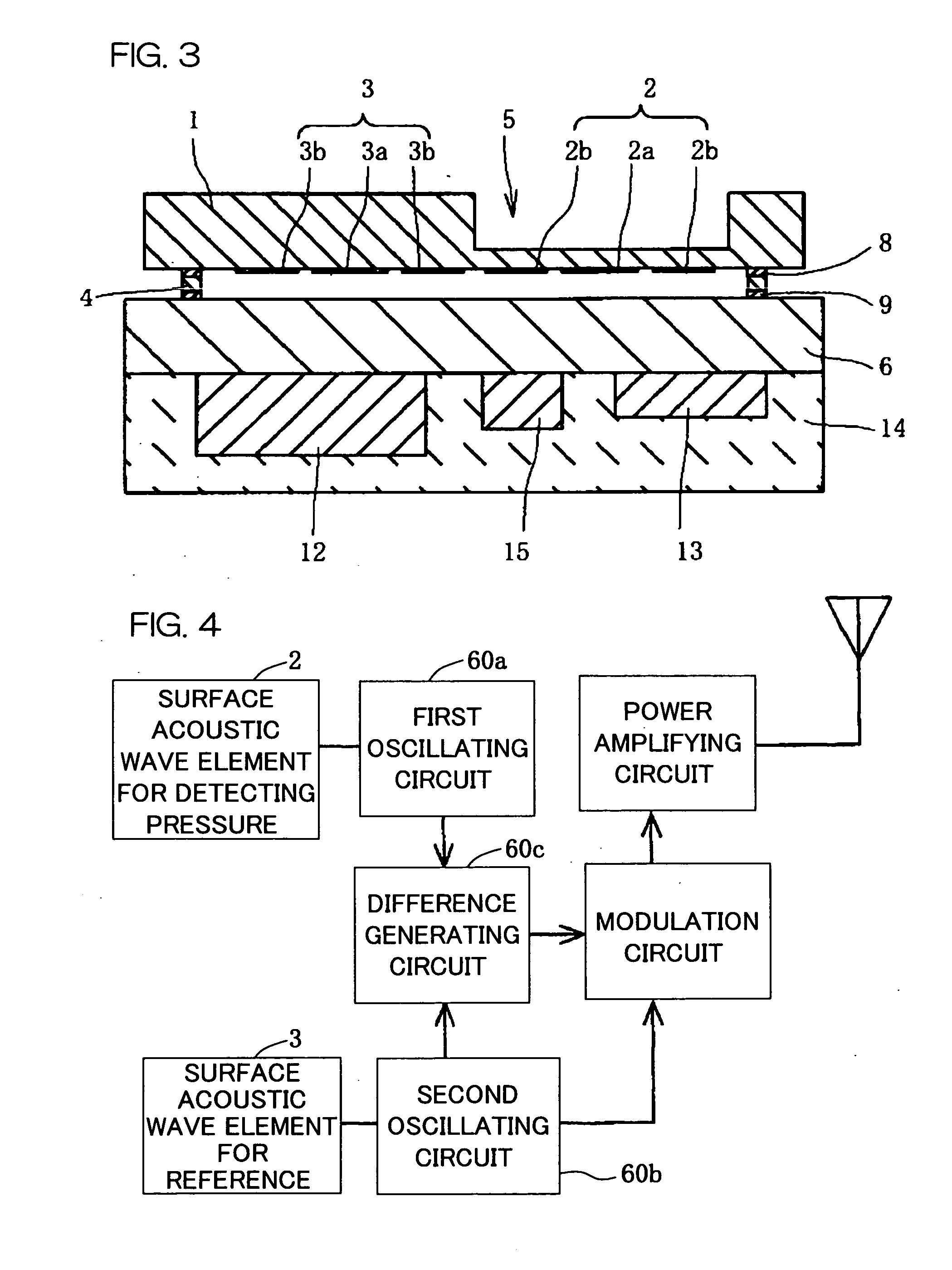
[0236]FIG. 24 is a circuit diagram showing an electrical construction of oscillating circuits and a difference generating circuit of the pressure sensor device.

[0237] The pressure sensor device mainly comprises the sensor substrate 1, the supporting substrate 6, an electronic part element 50, and a sealing member 4.

[0238] In the sensor substrate 1, the sensor section 11 deforms according to a pressure applied to the sensor substrate 1 to detect pressure fluctuation.

[0239] On the lower surface of the sensor substrate 1, the senso...


PUM


Abstract

A sensor substrate 1 having on its lower surface a surface acoustic wave element 2 for detecting pressure is mounted on a supporting substrate 6 through a sealing member 4 surrounding a sensor section 2. A sealing space S is formed by the sensor substrate 1, the supporting substrate 6, and the sealing member 4, and the surface acoustic wave element 2 for detecting pressure is sealed hermetically in the sealing space S. Reliability can be enhanced by protecting the surface acoustic wave element 2 from the external environment.

Description

TECHNICAL FIELD [0001] The present invention relates to a pressure sensor device to be used for monitoring an air pressure in a tire, which detects pressure fluctuations of gas or liquid and transmits electrical signals. The portion comprising an element for detecting pressure fluctuations is referred to as “sensor section” in this description, hereinafter. BACKGROUND ART [0002] Conventionally, as a pressure sensor device for detecting pressure fluctuations of gas or liquid, a type that detects fluctuations of an applied pressure as oscillation frequency changes of a sensor section has been used. [0003] As such a conventional pressure sensor device, as shown in FIG. 40 and FIG. 41, one is known structured so that a surface acoustic wave element 104 and a surface acoustic wave element 107 formed of comb-shaped electrodes are formed as elements of a sensor section on a piezoelectric substrate 101, and a region of the surface acoustic wave element 104 is set thinner than the region of ...

Claims


Application Information

Patent Timeline
IPC IPC(8): G01L9/00
CPCB60C23/0408G01L9/0025
Inventor MOMOSE, KAZUHISAMATSUO, KAORUSHIMOKIHARA, SHINICHIINOUE, HISAYUKI
Owner KYOCERA CORP
Why Eureka
Try Eureka