Light emitting device with adjustable reflector cup

a technology of light emitting device and reflector cup, which is applied in the direction of semiconductor devices for light sources, point-like light sources, lighting and heating apparatus, etc., can solve the problems of often being too much or too little light being cast on objects, and achieve the effects of low reflectivity, high reflectivity, and increased aggregate reflectivity of the bas

Active Publication Date: 2007-04-26
BENCH WALK LIGHTING LLC
View PDF9 Cites 11 Cited by
  • Summary
  • Abstract
  • Description
  • Claims
  • Application Information

AI Technical Summary

Benefits of technology

[0002] A light emitting device has a light emitting diode (LED), a reflector cup, and one or more adjustment mechanisms to control the intensity profile of light emitted from the light emitting device. The reflector cup has a base and a sidewall extending outward from the base. A base adjustment mechanism controls the total amount of light reflected from the base by controlling the aggregate reflectivity of the base. In an embodiment, the base adjustment mechanism includes an aperture having a comparatively low reflectivity that is configured to adjustably shield a varying amount of surface area of a reflective base structure having a comparatively high reflectivity. As a greater amount of the surface of the reflective base structure is increasingly exposed to light from the LED, the aggregate reflectivity of the base increases. As the available surface area of the reflective base structure is increasingly shielded from the LED, the aggregate reflectivity of the base decreases.
[0003] A sidewall adjustment mechanism controls the angle of the sidewall relative to the base. The sidewall can be formed from an aperture to achieve adjustability. As the angle of the sidewall relative to the base is widened, the field of view of the light emitting device is widened, spreading light over a greater area, but decreasing the concentration of light within the center portion of the field of view. As the angle of the sidewall relative to the base is narrowed, the field of view of the light emitting device is narrowed, focusing the light over a narrower area, but increasing the concentration of light within the center area of the field of view.
[0004] A vertical adjustment mechanism vertically raises or lowers the LED relative to the base. The vertical adjustment mechanism can include a motor driven shaft such as a linear actuator. As the LED is raised relative to the base, it approaches the top of the reflector cup, thereby widening the field of view of light emanating from the reflector cup. As the LED is lowered relative to the base, it recedes from the top of the reflector cup, thereby narrowing the field of view of light emanating from the reflector cup.

Problems solved by technology

A limitation inherent in the conventional light emitting devices of FIGS. 1A and 1B is that light emitted from the device is distributed over a fixed field of view, resulting in a fixed intensity profile.
Additionally, because the total volume of light from a conventional light emitting device is fixed, the volume of light being cast upon an object can often be too much, or too little.

Method used


Image

  • Light emitting device with adjustable reflector cup
  • Light emitting device with adjustable reflector cup
  • Light emitting device with adjustable reflector cup

Examples


Embodiment Construction

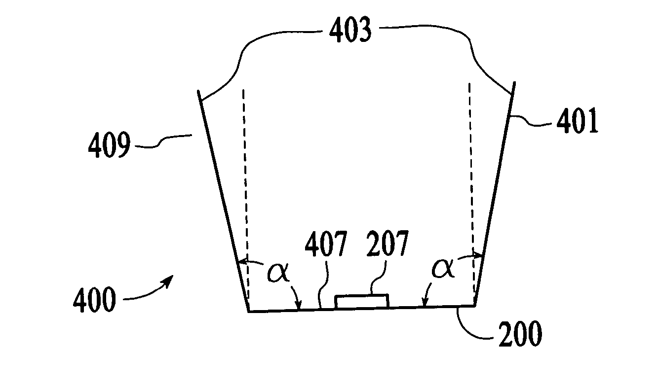
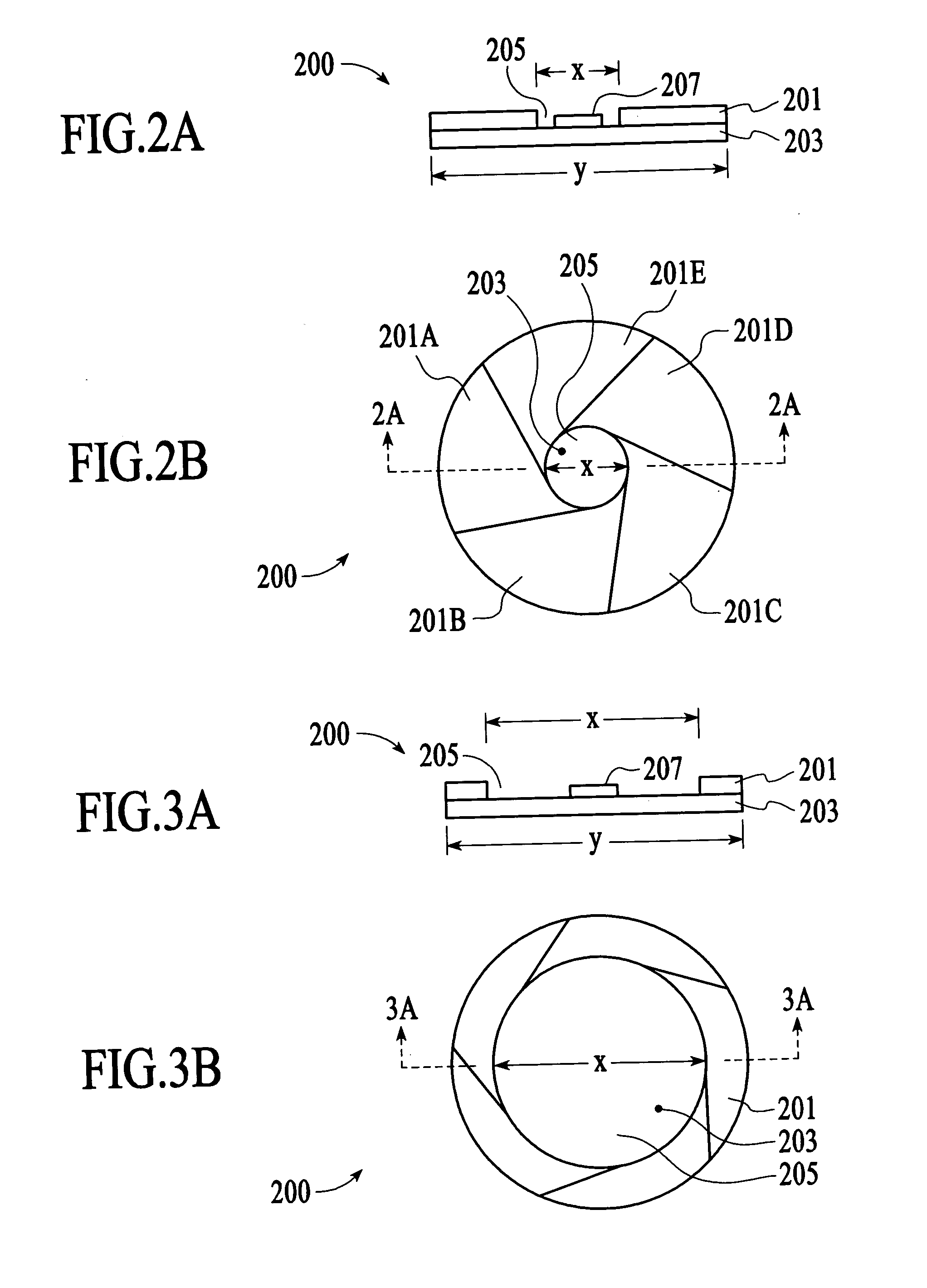
[0028] A light emitting device has a light emitting diode (LED), a reflector cup, and one or more adjustment mechanisms to control the intensity profile of light emitted from the light emitting device. The reflector cup has a base and a sidewall extending outward from the base. A base adjustment mechanism controls the total amount of light reflected from the base by controlling the aggregate reflectivity of the base. FIG. 2A depicts a side elevational cross-cut view of an adjustable base 200 of a reflector cup (sidewall not shown), and an LED 207 disposed proximate the base. The adjustable base 200 includes a reflective base structure 203 and a base adjustment mechanism. According to the embodiment of FIG. 2A, the base adjustment mechanism includes an adjustable base aperture 201 disposed above the reflective base structure. FIG. 2B is a top plan view of the adjustable base 200 of FIG. 2A. The adjustable base aperture 201 includes multiple aperture plates 201A-201E. The exact number...


PUM


Abstract

A light emitting device has a light emitting diode (LED), a reflector cup, and one or more adjustment mechanisms to control the intensity profile of light emitted from the light emitting device. The reflector cup has a base and a sidewall extending outward from the base. A base adjustment mechanism controls the total amount of light reflected from the base and into the beam of light emitted from the light emitting mechanism by controlling the aggregate reflectivity of the base. A sidewall adjustment mechanism controls the angle of the sidewall relative to the base. A vertical adjustment mechanism vertically raises or lowers the LED relative to the base.

Description

BACKGROUND OF THE INVENTION [0001] LEDs (light emitting diodes) are currently used in a variety of applications, replacing the incandescent bulb and conventional fluorescent light sources in applications such as flash cameras, full color sign display, traffic lights, bicycle lights, and an increasing number of other innovative uses. LEDs have the advantage of emitting light defined by select wavelengths, or defining a limited spectrum, thereby reducing energy expenditure found in incandescent bulbs that typically propagate unwanted wavelengths. FIG. 1A depicts a side elevational view of a conventional light emitting device 100 having a reflector cup 107 with a fixed sidewall 105, a fixed base 103, and an LED 101 disposed within the reflector cup at a fixed position. FIG. 1B is a top plan view of the light emitting device of FIG. 1A, showing the LED 101 in the center of the reflector cup, the fixed base 103 of the reflector cup surrounding the LED, and the fixed sidewall surrounding ...

Claims


Application Information

Patent Timeline
Patent Type & Authority Applications(United States)
IPC IPC(8): H01L33/00H01L33/60
CPCH01L33/60F21V7/16F21V11/10F21V14/02F21V14/04F21V14/06F21V14/08F21V17/02F21V19/02F21Y2101/02F21V7/18F21Y2115/10
Inventor GOON, WOOL KINMOK, THYE LINNNG, KEE YEANCHUA, JANET BEE YINCHEW, GIM ENGHELBING, RENE P.
Owner BENCH WALK LIGHTING LLC
Why Eureka
Try Eureka