
Electronic wearable device

a wearable device and electronic technology, applied in the direction of antenna details, slot antennas, antennas, etc., can solve the problems of not being able to use described structures in metal-covered devices, unable to incorporate antennas into wearable devices, and unable to use conductive materials in the device housing

Active Publication Date: 2007-04-26
SUUNTO OY
View PDF16 Cites 74 Cited by
  • Summary
  • Abstract
  • Description
  • Claims
  • Application Information

AI Technical Summary

Benefits of technology

[0011] It is an aim of the present invention to eliminate some of the problems of the prior art and to provide a wearable device having a novel antenna construction.
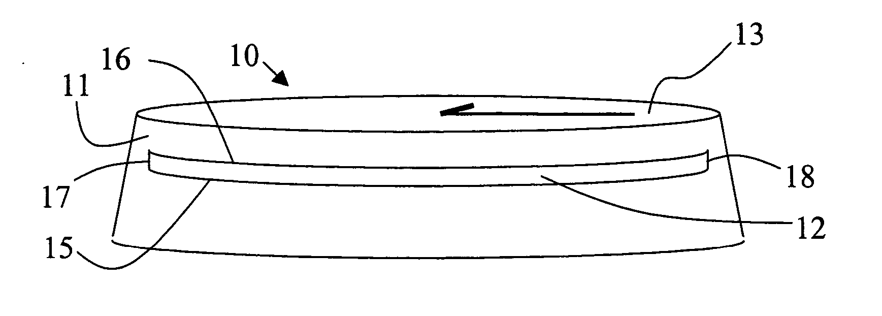
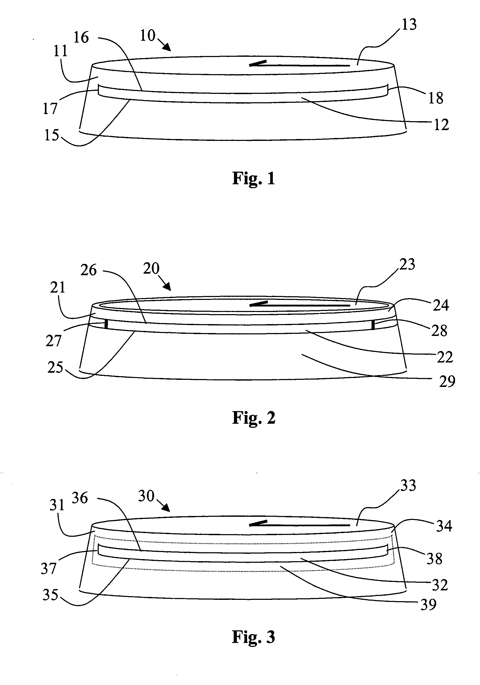
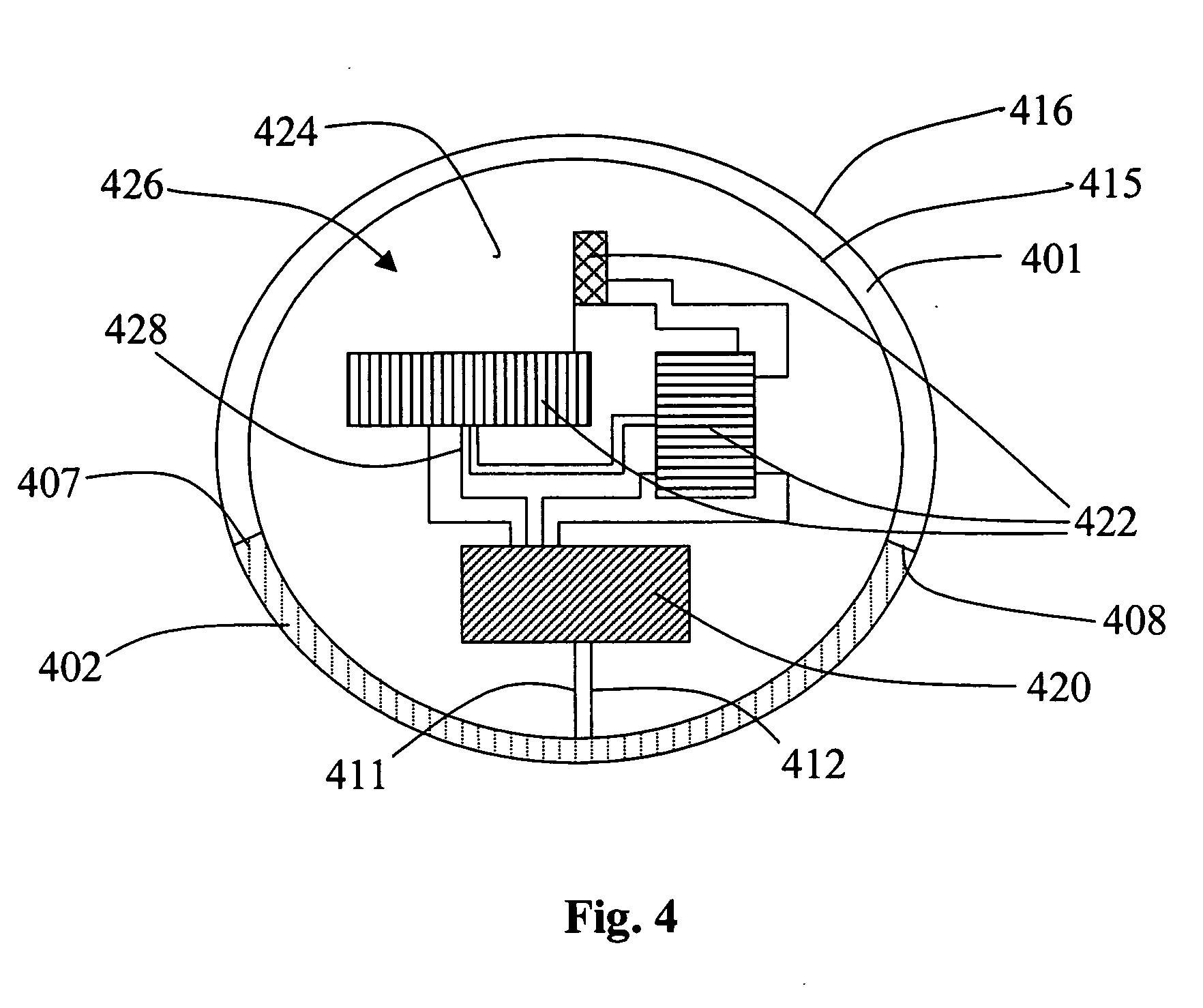
[0018] Considerable advantages are obtained by means of the invention. In particular, the invention allows the use of partly or fully conductive cover to be used in a wirelessly communicating wearable device without significant attenuation of signal due to the cover. In addition, a slot antenna placed on the outer cover is easy to manufacture and is relatively weakly coupled to other electronic and conductive parts of the device due to its peripheral location. The cover acts as a conductive cage causing the antenna to radiate primarily to the exterior of the device.
[0019] The slot can be formed to a metal cover in the manufacturing stage of the cover. Typically, such covers are fabricated from a single block of metal, whereby forming of the slot would be only a minor sub-step in that stage. Moreover, in the assembling stage of the device, no additional steps would be needed because of the antenna. Thus, such a solution does necessitate any complex mechanical or electrical arrangements within the device, whereby the number of components and further the size of the device can be kept small. Efficient utilization of the housing of the device as the radiating element gives also relatively free hands for placing of other components within the housing.
[0020] Placing the antenna on the outer housing of the device enables making the effective dimemsion of the antenna larger, and therefore using longer wavelengths, than if the antenna is placed in the interior parts of the device. In addition, directioning of radiation can be adjusted by the three-dimensional structure of the conductive portions of the cover.

Problems solved by technology

However, incorporating an antenna into a wearable device is a challenging task due to size limitations, great amount of electronic components in proximity to each other and due to the closeness of human body.
A major drawback of the wearable devices referred to above is that because the antenna is located deep inside the housing of the device, conductive materials can not be used in the housing of the device due to the resulting attenuation of the signal.
Thus, the described structures can not be used in metal-cased or metal-covered devices.
In addition, antenna takes a lot of space inside the device and couples easily to the circuitry of the device, whereby the placing of the parts has to be made taking into account the proximity of the antenna.

Method used


Image

  • Electronic wearable device
  • Electronic wearable device
  • Electronic wearable device

Examples


Embodiment Construction

[0028] The devices and antennas according to embodiments disclosed in this document below can be used for communicating, for example, with a peripheral device, such as a heart rate monitor belt (or other separate vital function-sensitive transmitter), speed and / or distance measuring foot or bike pod (separate motion-sensitive transmitter), a GPS receiver placed in a place in the vicinity of the device and transmitting location data to the wrist device (separate location-sensitive transmitter), or an environment-sensor. In addition, the device can communicate with another compatible wristop device, with a remote computing unit, such as a computer having a suitable adapter, in a wireless network, such as local or wide area network (LAN / WAN), in Bluetooth-applications or, for example, with a sports timing or performance monitoring system of a special kind. The antenna can also be used for receiving Global Positioning System (GPS) signals or in a mobile telephone network. Typically, the...


PUM


Abstract

The invention concerns a wrist-wearable electronic device comprising a slot antenna and a method of manufacturing the slot antenna. Such a device comprises an outer housing defining an assembly zone and a radio unit contained within the assembly zone. According to the invention the outer housing is made at least partly of conductive material and comprises an integral slot antenna formed in the conductive material portion thereof, the antenna being electrically connected to the radio unit. The invention provides a convenient antenna structure for wirelessly communicating wristop computers and the like.

Description

BACKGROUND OF THE INVENTION [0001] 1. Field of the Invention [0002] The present invention relates to wearable electronic devices. In particular, the invention concerns a wrist-worn device, such as a wristop computer, which has an antenna for communicating wirelessly with other electronic devices. In addition, the invention concerns a method for the manufacture of an antenna for wearable devices. [0003] 2. Description of Related Art [0004] Antennas have been assembled into wristop computers for some time for allowing wireless data transfer into and out of the device. However, incorporating an antenna into a wearable device is a challenging task due to size limitations, great amount of electronic components in proximity to each other and due to the closeness of human body. [0005] The patent application US 2002 / 0098807 discloses a wrist device with an integrated loop antenna. The loop is placed in the same plane with other electronic circuitry of the device such that some of the electr...

Claims


Application Information

Patent Timeline
IPC IPC(8): H01Q1/12
CPCH01Q1/273H01Q13/10
Inventor PUURI, HEIKKI
Owner SUUNTO OY
Learn More