

Light supply unit, illumination unit, and illumination system
a technology of illumination unit and light supply unit, which is applied in the direction of optical signalling, microscopy, photographic printing, etc., can solve the problems of reducing reducing the internal quantum efficiency, and affecting the efficiency of light extraction, so as to achieve efficient heat generation of semiconductor light emitting devices and efficiently adjust illumination intensities
- Summary
- Abstract
- Description
- Claims
- Application Information
AI Technical Summary
Benefits of technology
Problems solved by technology
Method used
Image

Examples
first embodiment
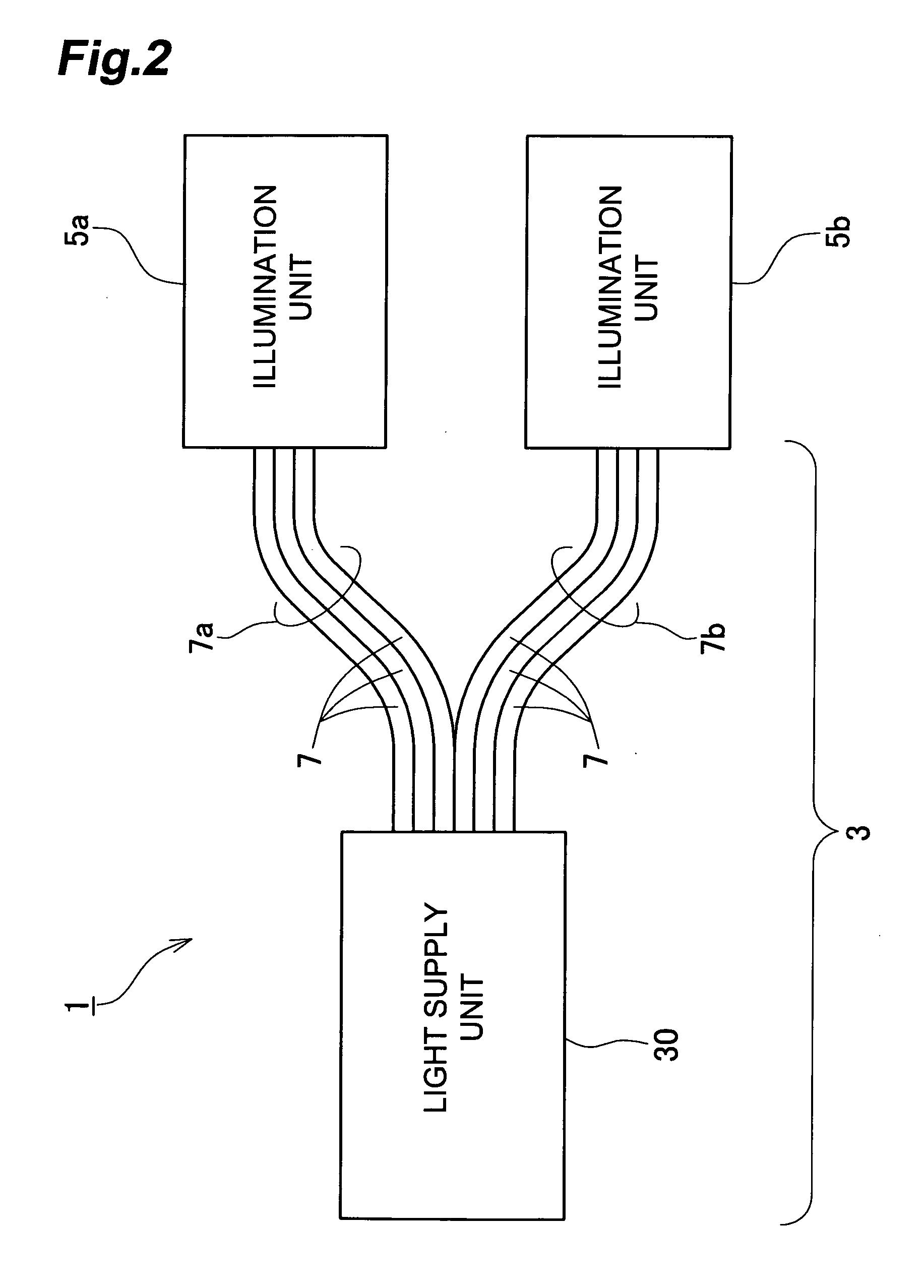
[0031]FIG. 2 is a block diagram showing an embodiment of the illumination system according to the present invention. Referring to FIG. 2, the illumination system 1 according to the present embodiment is provided with a light supply unit 3, and illumination units 5a and 5b. The light supply unit 3 has a main body 30 and two optical fiber groups 7a and 7b. The optical fiber groups 7a and 7b include a plurality of optical fibers 7. The optical fiber groups 7a and 7b extend from one ends, which are the first ends in the present embodiment, to their respective illumination positions different from each other. The first ends of the optical fibers 7 are optically coupled to the main body 30 of the light supply unit 3. The other ends, which are the second ends in the present embodiment, of the optical fibers 7 belonging to the optical fiber group 7a are optically coupled to the illumination unit 5a. The other ends, which are also the second ends in the present embodiment, of the optical fib...
first modified embodiment
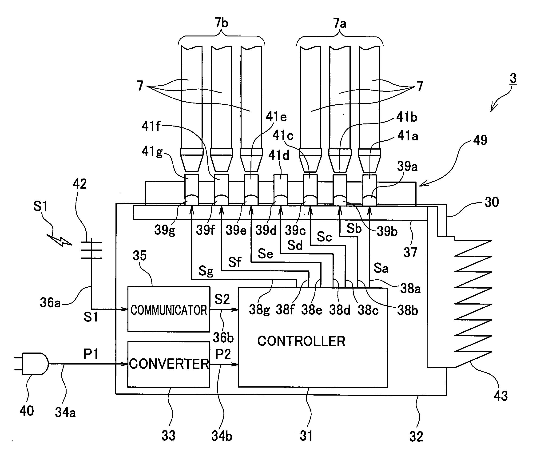
[0058]FIG. 10 is a configuration diagram showing a first modified embodiment of the light supply unit 3 of the above-described embodiment. With reference to FIG. 10, the light supply unit 3a of the present modified embodiment is further provided with a cooling device 44, in addition to the configuration of the light supply unit 3 of the above embodiment. The cooling device 44 is a device for cooling the light emitting devices 39a-39g, and adopts, for example, an air cooling or water cooling system. In the present modified embodiment the cooling device 44 is contained in the housing 32 and connected to the substrate 37. When the light supply unit 3 is provided with the cooling device 44 as in this configuration, the unit is able to more efficiently radiate the heat generated in the light emitting devices 39a-39g.
second modified embodiment
[0059]FIG. 11 is a configuration diagram showing a second modified embodiment of the light supply unit 3 of the above-described embodiment. With reference to FIG. 11, the light supply unit 3b of the present modified embodiment is further provided with a water heater 48, in addition to the configuration of the light supply unit 3 of the aforementioned embodiment. The water heater 48 is preferably contained in the housing 32. The water heater 48 is a device for heating water by the heat from the light emitting devices 39a-39g. The light supply unit 3b of the present modified embodiment is provided with a radiator plate 46 instead of the radiator plate 43 of the aforementioned embodiment. The radiator plate 46 provides the water heater 48 the heat transmitted through the substrate 37 from the light emitting devices 39a-39g. The water heater 48 heats cool water C flowing in a tube, by the heat from the radiator plate 46, and supplies hot water H to the outside. When the light supply uni...
PUM
 Abstract
Description
Claims
Application Information