
Medical image processing system and medical image processing method

a technology of medical image and image processing, applied in the field of display of computerized tomography (ct) images, can solve the problems of difficult reproduction of the direction of coronary angiography imaging from the direction of display of the ct image, subject may be exposed to x-rays, and difficult reproduction of the projection direction of the coronary angiography imaging direction, etc., to achieve a smaller amount of exposure to a subject, reduce the risk of x-ray exposure, and reduce the risk of x

Active Publication Date: 2007-04-26
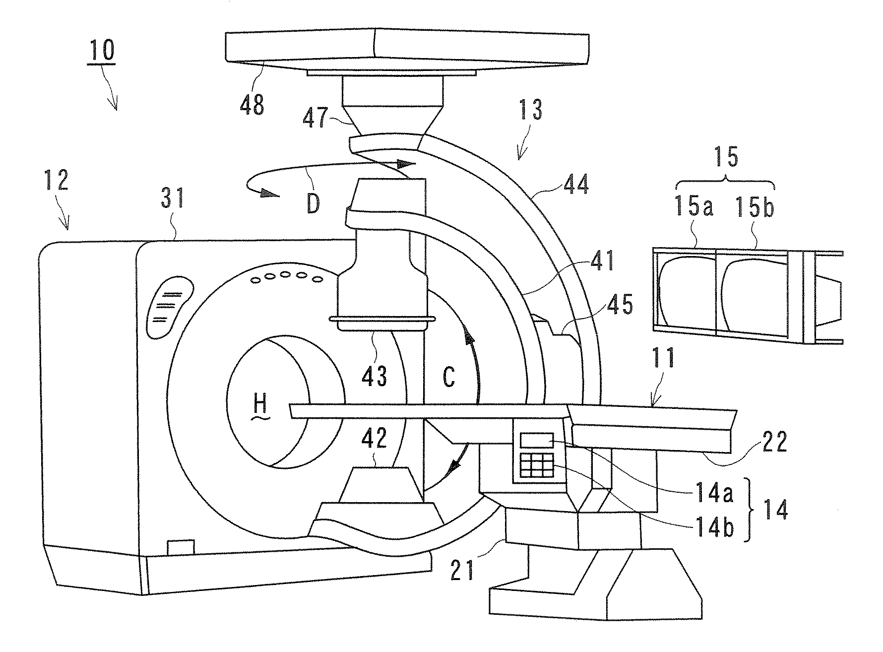
TOSHIBA MEDICAL SYST CORP
View PDF7 Cites 17 Cited by
  • Summary
  • Abstract
  • Description
  • Claims
  • Application Information

AI Technical Summary

Benefits of technology

[0012] In addition, the present invention has taken into consideration the above-described problems, and it is an object of the present invention to provide a medical image processing system and a medical image processing method such that a characteristic of blood vessels such as the evaluation of the rate of a narrowing can be evaluated more accurately by displaying a CT curved-planer projected image in the same direction of a projection as a direction of imaging of a anglo-image.
[0013] In addition, the present invention has taken into consideration the above-described problems, and it is an object of the present invention to provide a medical image processing system and a medical image processing method such that PCI can be performed in a shorter operation time and with a smaller amount of exposure to a subject.
[0019] In addition, according to the present invention to provide a medical image processing system and a medical image processing method, a characteristic of blood vessels such as the evaluation of the rate of a narrowing can be evaluated more accurately by displaying a CT curved-planer projected image in the same direction of a projection as a direction of imaging of a angio-image.
[0020] In addition, according to the present invention to provide a medical image processing system and a medical image processing method, PCI can be performed in a shorter operation time and with a smaller amount of exposure to a subject.

Problems solved by technology

However, the strict reproduction of the same direction of the projection as the direction of the imaging of the angio-image on the CT-image is difficult because of the difference in modality or since the generation of CT-images in the same heartbeat phase timing as that of angio-images is difficult.
However, the definition (search) of the direction of imaging of the angio-image takes time, and a subject may be exposed to X-rays, which is a problem.
However, the reproduction of the direction of imaging of the angio-image in coronary angiography from the direction of display of the CT-image is difficult unless the projected image of the target vessel is only used.

Method used


Image

  • Medical image processing system and medical image processing method
  • Medical image processing system and medical image processing method
  • Medical image processing system and medical image processing method

Examples


first embodiment

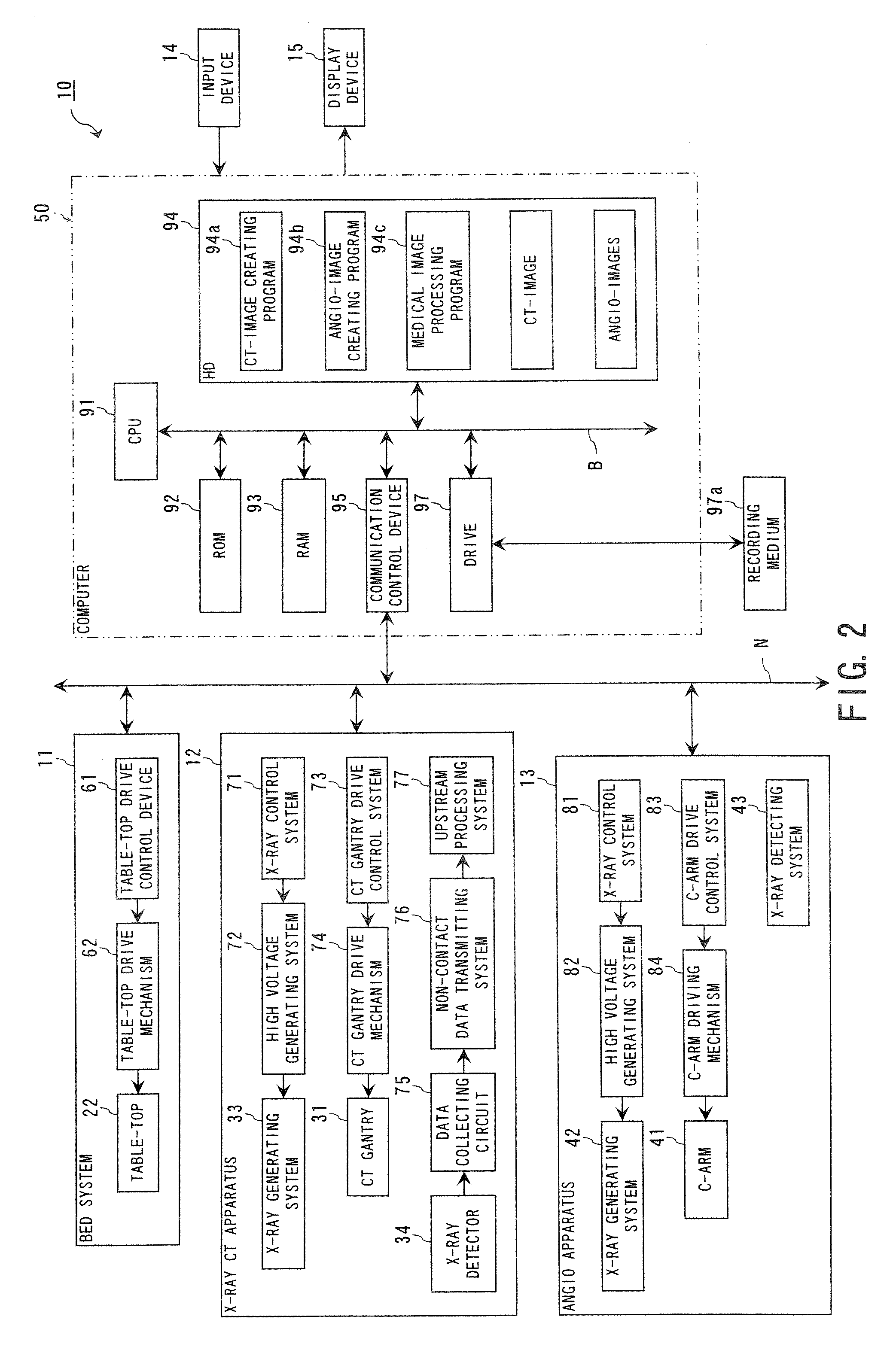
[0059]FIG. 3 is a functional block diagram showing a medical image processing system functioning by the execution of the medical image processing program 94c.

[0060] The CPU 91 executes the medical image processing program 94c installed in the computer so that the computer 50 can function as an angio-image obtaining unit 101, an angio-image imaging direction obtaining unit 102, a CT-image obtaining unit 103, a blood vessel part extracting unit 104, a projected image generating unit 105, an angiogram extracting unit 106, a display control unit 107 and a blood vessel characteristic evaluating unit 108. The computer 50 may function as a direction-of-vision correspondence information generating unit (not shown). The CPU 91 executes the medical image processing program 94c installed in the computer 50 so that the computer 50 can function as a medical image processing system.

[0061] The angio-image obtaining unit 101 has a function to obtain a required angio-image 94e selected by an opera...

second embodiment

[0097]FIG. 9 is a functional block diagram showing a medical image processing system functioning as a result of the execution of the medical image processing program 94c.

[0098] The CPU 91 executes the medical image processing program 94c installed in the computer so that the computer 50 can function as an angio-image obtaining unit 101, an angio-image imaging direction obtaining unit 102, a CT-image obtaining unit 103, a blood vessel part extracting unit 104, a projected image generating unit 105, a angiogram extracting unit 106, a direction of projection defining unit 109, a display control unit 107 and a blood vessel characteristic evaluating unit 108.

[0099] The direction of projection defining unit 109 has a function to get a direction of the projection of the three-dimensional CT curved-planer projected image corresponding (resembling) to the direction of imaging of the angio-Image 94e, by comparing the blood vessel part contained in the three-dimensional CT curved-planer proj...


PUM


Abstract

IVR-CT apparatus has an angio-image obtaining unit, an angio-image imaging direction obtaining unit, a CT-image obtaining unit, a blood vessel part extracting unit, a projected image generating unit and a display control unit. The angio-image obtaining unit obtains a required angio-image from multiple chronological angio-images. The angio-image imaging direction obtaining unit obtains a direction of imaging as incidental information included in data on the required angio-image. The CT-image obtaining unit obtains a three-dimensional CT-image corresponding to the required angio-image. The blood vessel part extracting unit extracts a blood vessel part in the three-dimensional CT-image. The projected image generating unit generates a three-dimensional projected image by projecting the blood vessel part, and a three-dimensional projected image corresponding to a direction of a projection after a manual operation operates the direction of the projection. The display control unit makes display the three-dimensional projection image and the angio-image one over another.

Description

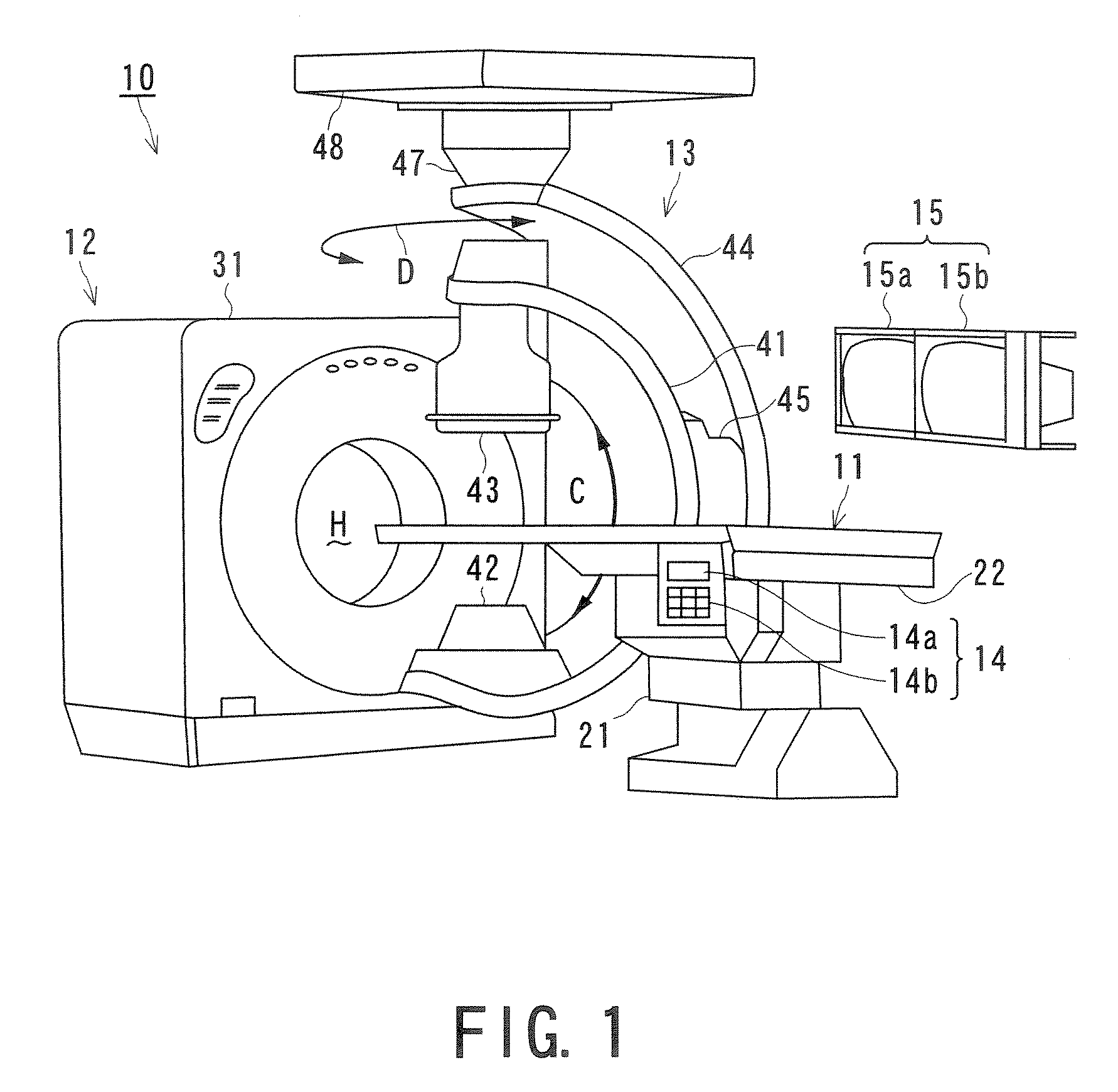
BACKGROUND OF THE INVENTION [0001] 1. Field of the Invention [0002] The present invention relates to a technology for displaying a computerized tomography (CT) image and, in particular, to a medical image processing system and method for evaluating the rate of a narrowing of a coronary and / or a characteristic of a blood vessel by defining a plane to project a CT-image to be displayed. [0003] 2. Description of the Related Art [0004] An interventional Radiology-computerized tomography (IVR-CT) apparatus has been proposed which has a combination of an X-ray CT apparatus and a radiographic X-ray apparatus including a C-arm, which is a substantially C-shaped supporting device. [0005] The X-ray CT apparatus includes a CT base (gantry) having a hollow part around which an X-ray generating source and an X-ray detector are provided. A subject (patient) mounted on a table-top is introduced into the hollow part, and X-ray transmission information (projection data) in directions on the subject ...

Claims


Application Information

Patent Timeline
IPC IPC(8): H05G1/02
CPCA61B6/032A61B6/4441A61B6/481A61B6/504A61B6/5235
Inventor FUJISAWA, YASUKO
Owner TOSHIBA MEDICAL SYST CORP
Learn More