Polarization compensation in a coherent optical receiver

a coherent optical receiver and polarization compensation technology, applied in the field of optical communication networks, can solve the problems of preventing successful deployment in “real-world” installed communications networks, distorted optical signals received through conventional optical links by significant amounts of chromatic dispersion (cd) and polarization dependent impairments

Active Publication Date: 2007-04-26
CIENA
View PDF18 Cites 71 Cited by
  • Summary
  • Abstract
  • Description
  • Claims
  • Application Information

AI Technical Summary

Benefits of technology

[0014] Accordingly, an object of the present invention is to provide methods enabling a polarization compensation of high speed polarization transients.

Problems solved by technology

However, receivers based on coherent detection techniques have suffered disadvantages that have, to date, prevented successful deployment in “real-world” installed communications networks.
In particular, optical signals received through conventional optical links are distorted by significant amounts of chromatic dispersion (CD) and polarization dependent impairments such as Polarization Mode Dispersion (PMD), polarization angle changes and polarization dependent loss (PDL).
These problems are compounded for polarization-division multiplexed signals, in which each transmitted polarization contains a respective different data signal.
However, Noé does not provide any teaching as to how this would be done.
However, limitations of optical components, and the time-varying amount of compensation required, make this objective very difficult to achieve.
Additionally, optical compensators are expensive and introduce significant optical losses.
The additional (or higher-performance) optical amplifiers required to provide this increased gain further increases the total cost of the communications system.
In addition, the presence of optical dispersion compensators and high performance amplifiers distributed along the length of the link provides a significant technical barrier to system evolution.
While the system of Noé is satisfactory in a laboratory setting, it cannot track high speed transients of the type encountered in real-world communications networks.
In addition, the system of Noé tends to fail in the presence of severe Chromatic Dispersion (CD), at least in part due to failure of the clock recovery circuit as inter-symbol interference (ISI) increases, and consequent uncertainty of the sample timing of the A / D converters.
Signals that are severely distorted by chromatic dispersion (e.g. greater than about 1000 picoseconds per nanometer) are spread out to such a degree that it is not feasible to recognize the symbols, and so one is not able to distinguish the two polarization division multiplexed signals from the two received polarizations.

Method used


Image

  • Polarization compensation in a coherent optical receiver
  • Polarization compensation in a coherent optical receiver
  • Polarization compensation in a coherent optical receiver

Examples


Embodiment Construction

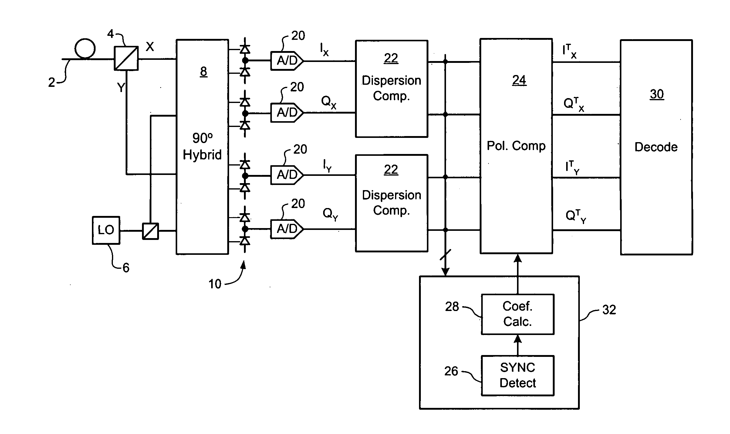
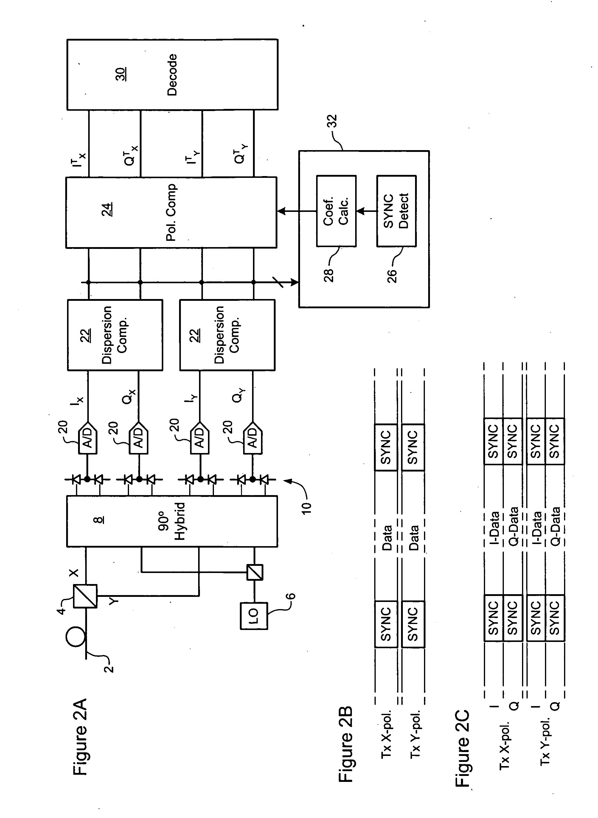
[0023] The present invention provides methods and systems enabling robust compensation of polarization dependent impairments, in the presence of severe dispersion. Embodiments of the invention are described below, by way of example only, with reference to FIGS. 2-4.

[0024] In general, the present invention operates by implementing separate training loops for training the dispersion and polarization compensation functions. In one embodiment, this is implemented by separating the dispersion and polarization compensation functions into discrete filter blocks cascaded within a common data path or pipeline, and then implementing a respective different training loop for training each filter block. In this embodiment, the digital sample stream generated by sampling the optical signal is first processed to compensate chromatic dispersion (CD). The dispersion compensated sample stream is then processed to compensate polarization dependent impairments. Separation of the dispersion and polariz...


PUM


Abstract

A method of processing a stream of digital samples of an optical signal received by a coherent optical receiver. The digital sample stream is processed to generate a dispersion compensated sample stream. The dispersion compensated sample stream is then processed to compensate polarization dependent impairments of the optical signal.

Description

CROSS-REFERENCE TO RELATED APPLICATIONS [0001] This application claims benefit under 35 U.S.C. 119(e) from U.S. Provisional Patent Application Ser. No. 60 / 728,751, entitled Automatic Gain Control, which was filed on Oct. 21, 2005, under attorney docket No. 13528-250USPR.MICROFICHE APPENDIX [0002] Not Applicable. TECHNICAL FIELD [0003] The present invention relates to optical communications networks, and in particular to a method and apparatus for implementing electronic polarization compensation of optical signals received through an optical communications network. BACKGROUND OF THE INVENTION [0004] In the optical communications space, techniques used to detect data modulated onto an optical communications signal may be broadly group into two classes, namely “direct” detection and “coherent” detection. In “direct” detection techniques, the optical signal is made incident on a photodetector. The electrical current appearing at the photodetector output is proportional to the optical p...

Claims


Application Information

Patent Timeline
Patent Type & Authority Applications(United States)
IPC IPC(8): H04B10/12
CPCH04B10/2572H04B10/60H04B10/6161H04B10/6162H04B10/64H04J14/06H04L7/041
Inventor BONTU, CHANDRAO'SULLIVAN, MAURICEROBERTS, KIM B.SUN, HANWU, KUANG TSAN
Owner CIENA
Why Eureka
Try Eureka