In-guide control of optical propagation

a control device and optical propagation technology, applied in the direction of optics, optical light guides, instruments, etc., can solve the problems of stability of the system, out-of-fiber systems, and difficulty in manufacturing the components of the micro-optical system, and achieve high efficiency

Inactive Publication Date: 2005-02-22
PHOTINTECH
View PDF16 Cites 33 Cited by
  • Summary
  • Abstract
  • Description
  • Claims
  • Application Information

AI Technical Summary

Benefits of technology

An object of the present invention is to provide a highly efficient optical device of In-Fiber control of optical propagation.

Problems solved by technology

Out-of-Fiber systems suffer numerous disadvantages, including difficulties manufacturing the micro-optical system components, stability of the system during service, and the high optical losses imposed by such systems.
Losses are encountered within the micro-optical system, and more than 1 dB total loss will be encountered when coupling the light back into the transmission fiber.
As a result, Out-of-Fiber systems typically require more optical amplifiers, which further increases the cost of the system.
However, the performance of many optical components is frequently affected by environmental conditions and dynamic network configuration changes, and thus is strongly time varying.
Both of these devices are highly temperature sensitive and power consuming, both of which are undesirable, particularly in compact integrated geometries.
Because these devices require a side-polished fiber, the optical properties of which are also highly dependent on the radius of curvature and the distance between the polished surface and the fiber core, they tend to be difficult to manufacture.
Finally, because of the curvature and asymmetry of the side-polished fiber, its optical performance may be polarization dependent, which in many cases is undesirable.
However, in contrast to FBG-based devices, the period ΛLPG and spectral bandwidth ΔλLPG of LPGs are typically very large (up to 1000 times larger than for narrowband FBG) and are not well adapted for narrow band (e.g., single WDM channel) applications.
However, this solution also is very limited since it inevitably introduces losses of light because of the complex refractive index of the material forming the electrode.
These conditions limit the application of that device as an efficient, low loss and narrowband-tuning element.
However, the thermal and mechanical methods, which affect the core zone of the fiber, are not efficient.

Method used


Image

  • In-guide control of optical propagation
  • In-guide control of optical propagation
  • In-guide control of optical propagation

Examples


Embodiment Construction

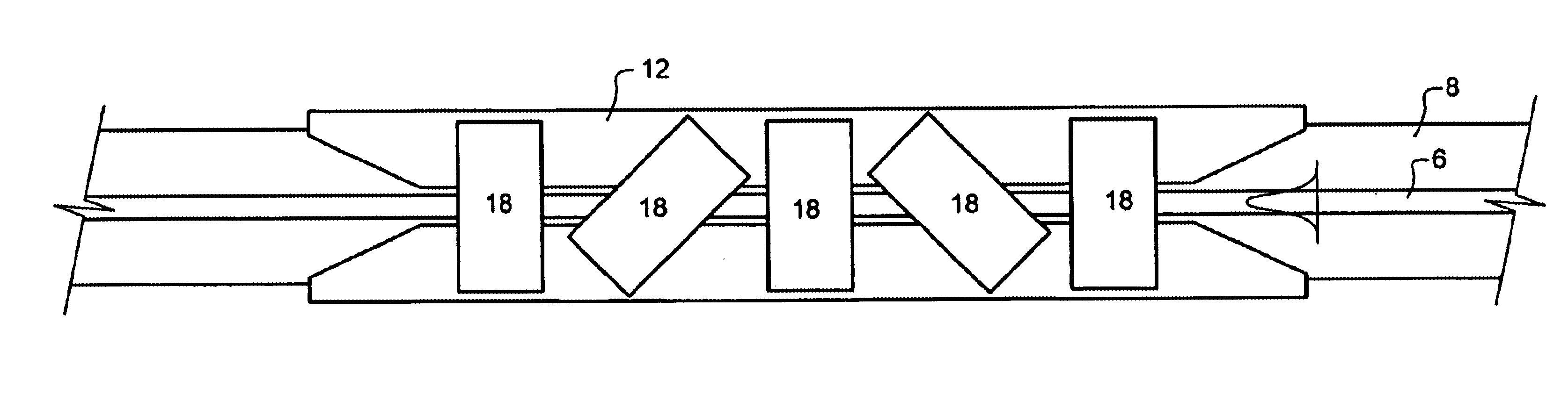
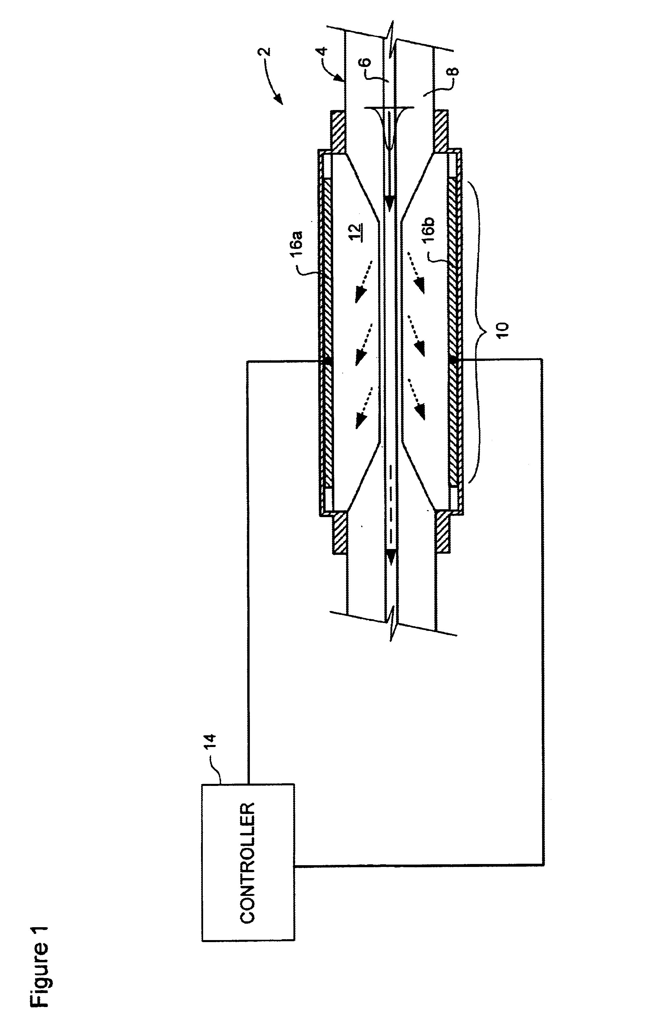
The present invention provides an optical device designed to control propagation of light within the core of an optical waveguide, such as a fiber. Variants of the optical device may be used in optical communication systems as a tunable filter, optical attenuator, delay line etc. FIG. 1 schematically illustrates principle elements of an embodiment of the present invention.

As shown in FIG. 1, the optical device 2 generally comprises an optical waveguide 4 having a core 6 surrounded by a cladding 8 having a substantially fixed index of refraction. A control region 10 is formed in the waveguide 4, in which a radial thickness of the cladding 8 is reduced to less than the penetration depth of an evanescent field of light propagating in the waveguide core 6. A variable-index material 12 is disposed around the cladding 8 at least within the control region 10, and thus is capable of interaction with the evanescent field of light in the core 6. The variable-index material 12 has an index of ...


PUM

PropertyMeasurementUnit
index of refractionaaaaaaaaaa
radial thicknessaaaaaaaaaa
evanescent fieldaaaaaaaaaa

Abstract

We propose a dynamically tunable electro-optic cladding using our proprietary electro-optic material, applied to various circular and planar wave-guides along with specific electrode configuration and excitation electric field format appropriate to that material. Based on the evanescent field coupling phenomena, the proposed device may be used in variable optical attenuators, tunable filters and couplers, etc. Different design of applied electrodes and optical properties of controllable refractive index materials allow polarization dependent or independent, as well as direct or inverse operation regimes of proposed devices.

Description

MICROFICHE APPENDIXNot Applicable.TECHNICAL FIELDThe present invention relates to controllable optical devices, and in particular to controllable optical devices for controlling the propagation of light in an optical waveguide.BACKGROUND OF THE INVENTIONAs is well known in the art, the successful implementation of optical communications systems requires devices capable of reliably controlling the propagation of light. Basic optical processing functions required in optical communications include, but are not limited to: optical modulation (which includes amplification and attenuation of optical power); phase control (delay); and switching. In Wavelength Division Multiplexed (WDM) and Dense Wavelength Division Multiplexed (DWDM) communications systems, significant channel power imbalance may be generated and channel equalization become necessary where the above noted basic functions must be performed on a per-channel basis.In modern high performance optical communications systems, dat...

Claims


Application Information

Patent Timeline
Patent Type & Authority Patents(United States)
IPC IPC(8): G02F1/01G02F1/1337G02F1/13
CPCG02F1/0118G02F1/1337G02F2203/48G02F2203/055G02F2202/022
Inventor GALSTIAN, TIGRANZOHRABYAN, ARMENDUMONT, DANYTORK, AMIRBIRABASSOV, ROUSLAN
Owner PHOTINTECH
Why Eureka
Try Eureka