Folding converging light into a lightpipe

a technology of converging light and lightpipe, which is applied in the direction of instruments, lighting support devices, polarising elements, etc., can solve the problems of increasing costs, reducing and reducing the efficiency of light sources, so as to achieve the effect of increasing the focal ratio of light sources

Inactive Publication Date: 2005-02-17
JDS UNIPHASE CORP
View PDF40 Cites 30 Cited by
  • Summary
  • Abstract
  • Description
  • Claims
  • Application Information

AI Technical Summary

Benefits of technology

[0015] wherein the converging beam of light passing through the prism has a second cone angle less than the first cone angle, effectively increasing the focal ratio of the light source, which effectively provides extra distance between the light source and the lightpipe.

Problems solved by technology

Unfortunately, light collection optics operate at a low focal ratio, e.g. approximately F / 1, which causes the cone of light exiting the light source to converge rapidly as it approaches' the entrance to the lightpipe, thereby leaving little or no room to fold the light without causing a vignetting effect, resulting in a loss of luminous flux.
However, these folds are not typically positioned at the input or output ends of the lightpipe, because the high flux levels of the light at those points could crack or melt the flat mirrors or cause damage to the reflective coating thereon.
However, this solution has increased costs, requires more space, and results in a decrease in lumens due to the addition of the lens system.

Method used


Image

  • Folding converging light into a lightpipe
  • Folding converging light into a lightpipe
  • Folding converging light into a lightpipe

Examples


second embodiment

[0027]FIG. 4 illustrates the present invention in which total internal reflection is used to reflect the beam of light 2 off of the third face 35 instead of a coating. A tapered lightpipe 38 replaces the original lightpipe 3 to ensure that the TIR condition is not defeated. Accordingly, the use of the prism 30 with an index of refraction greater than air ensures that the beam of light 2 is reflected providing the extra distance required between the light source 1 and the lightpipe 3 to do so, and without the use of flat mirrors or coatings.

third embodiment

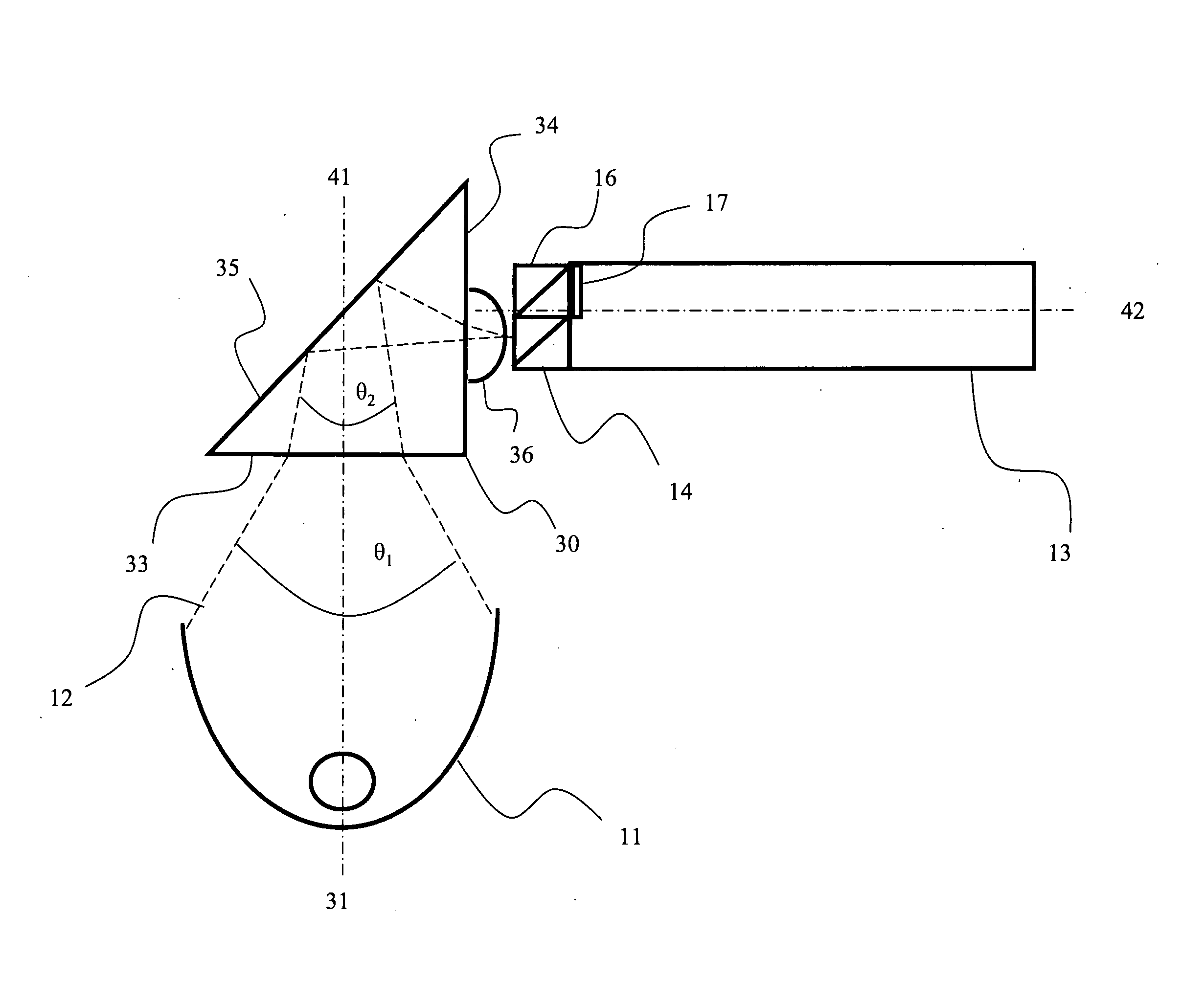
[0028]FIG. 5 illustrates the present invention comprising a polarization-dependent front end unit for use in a polarization dependent light engine system, such as the one illustrated in FIG. 2. As in FIG. 2, the light source 11, with optical axis 41, produces a high-flux, rapidly-converging beam of light 12 for input the lightpipe 13, which is defined by longitudinal axis 42. The first polarization beam splitter 14 passes the light of a first polarization, e.g. p-polarization, while reflecting light of a second polarization, e.g. s-polarization. The second beam splitter 16 reflects the s-polarized light again through the polarization rotator 17 in the direction of the lightpipe 3. In this arrangement, the prism 30 (as in FIG. 3) is used to reflect the light from the lights source 11 to the first polarization beam splitter 14.

fourth embodiment

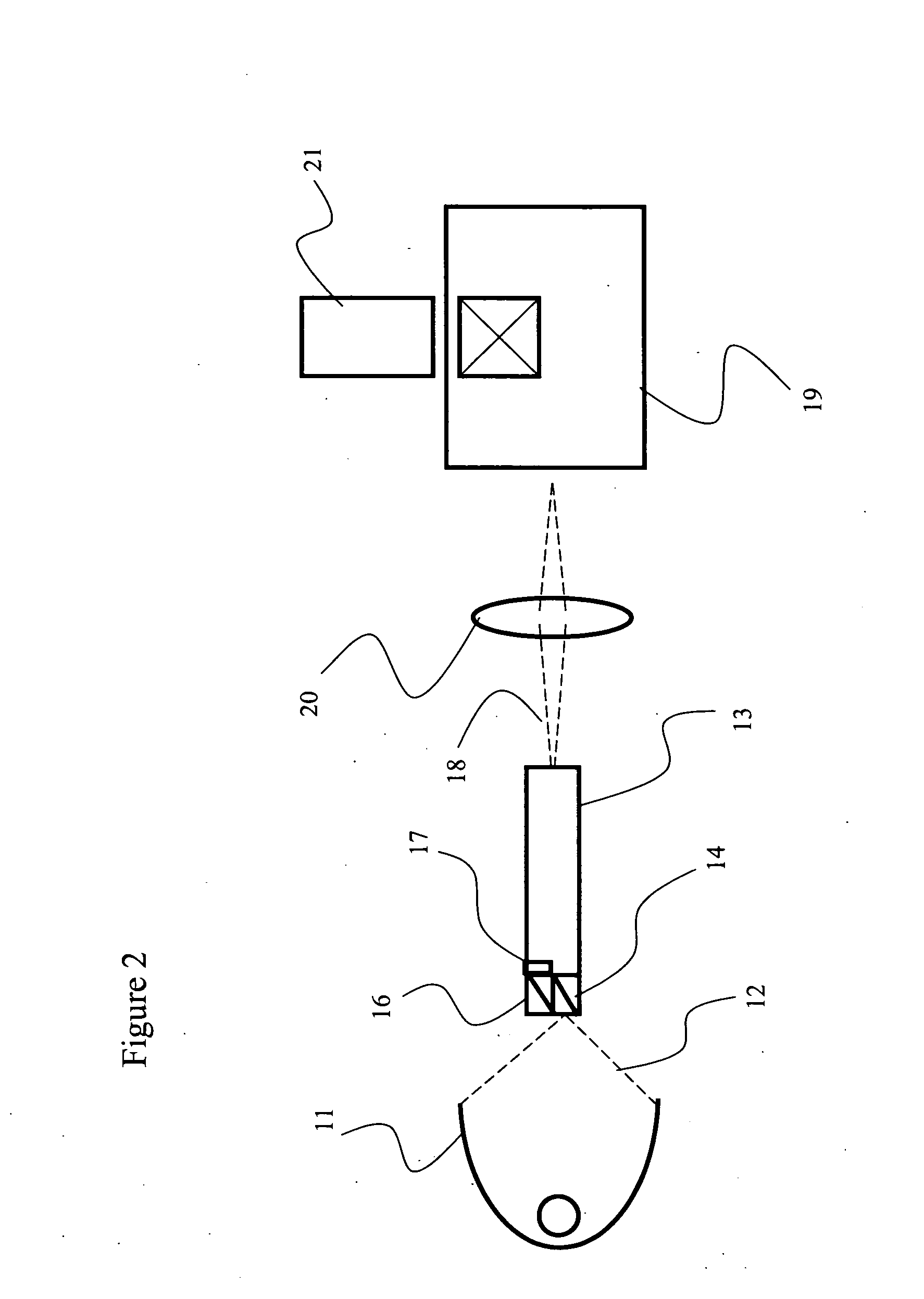
[0029] the present invention, illustrated in FIG. 6, provides a polarization-dependent front end unit in which the light source 11 produces a high-flux, rapidly-converging, beam of light 12 for input the lightpipe 13. Instead of positioning the prism 30 between the light source 11 and the first polarization beam splitter 14, a first polarization beam splitter 45 is positioned in the path of the beam of light 12 for reflecting the light of a first polarization, e.g. s-polarization, while passing the light of the orthogonal polarization, e.g. p-polarization, to a prism 46. The light of the second polarization is reflected off of the air / prism interface 47 by total internal reflection through a polarization rotator 48 into the lightpipe 13. In this arrangement, the second PBS 16 can be eliminated, and replaced by the prism 46. The air / prism interface 47 may or may not have a polarization-dependent coating to enhance reflection.


PUM


Abstract

The present invention relates to a folded front end unit used in a light engine of a projection display device. The front end unit comprises a light source for generating a beam of light, and a lightpipe for providing spatial uniformity to the beam of light. Polarization-dependent front end units include polarization beam splitters for separating the light into orthogonally polarized sub-beams, and a polarization rotating element, e.g. a waveplate, for rotating the polarization of one of the sub-beams. In accordance with the present invention, a prism is positioned between the light source and the lightpipe for reflecting the light into the lightpipe. The difference in refractive index between the air and the prism decreases the cone angle of the beam of light enough to effectively increase the distance between the light source and the lightpipe to compensate for the added distance required to fold the light.

Description

CROSS-REFERENCE TO RELATED APPLICATIONS [0001] The present invention claims priority from U.S. Patent Application No. 60 / 495,241 filed Aug. 14, 2003, which is incorporated herein by reference.TECHNICAL FIELD [0002] The present invention relates to folding converging light into a lightpipe, and in particular to a compact light engine for a projection display device, including a prism for folding converging light from a light source into a lightpipe. BACKGROUND OF THE INVENTION [0003] Conventional light engines for projection display devices, such as projectors and projection televisions, include a powerful light source for generating light, relay optics for transmitting the light, an image engine for converting the light into primary colors and selecting the appropriate color for each pixel, and projection optics for projecting the light onto a screen. [0004] A Digital Light Processing (DLP®) system is illustrated in FIG. 1, and includes a light source 1 for focusing light 2 into a l...

Claims


Application Information

Patent Timeline
Patent Type & Authority Applications(United States)
IPC IPC(8): G02B27/00G02B27/09G02B27/28
CPCG02B27/0905G02B27/0994G02B27/283G03B21/208H04N9/3197G03B21/2073H04N9/3152
Inventor FERRI, JOHNNEWELL, MICHAELPENTICO, CLARK
Owner JDS UNIPHASE CORP
Why Eureka
Try Eureka