
Multilevel pulse position modulation for efficient fiber optic communication

a fiber optic communication and multi-level technology, applied in the field of optical fiber communication systems, can solve the problems of limiting the aggregate power that can be transmitted through a single dwdm optical fiber, placing limits on the aggregate launch power, and limiting the number of wdm channels that can be combined for transmission on a single fiber, so as to increase the number of channels, and reduce the average transmitted power

Inactive Publication Date: 2007-04-26
INTERSIL INC
View PDF5 Cites 53 Cited by
  • Summary
  • Abstract
  • Description
  • Claims
  • Application Information

AI Technical Summary

Benefits of technology

[0017] The present invention can be used to decrease the average transmitted power per Wavelength Division Multiplexed (WDM channel) using multilevel amplitude modulation in conjunction with pulse position modulation (PPM). The multilevel PPM method of the present invention does not entail any tradeoff between decreased power per channel and channel bandwidth, allowing for a lower average transmitted power compared to OOK with no reduction in aggregate data rate. Therefore, multilevel PPM is applicable to high-speed DWDM systems where the maximum number of channels is currently limited by nonlinear effects in the fiber. This modulation technique can enable an increased number of channels in DWDM systems, thereby increasing aggregate data rates within those systems.
[0018] The present invention enables the combination of N data streams into one m-level amplitude modulated n-PPM (n available temporal positions within each transmitted cell) data stream, where m·n=2N. The m levels of amplitude modulation combined with the n chip positions within each cell allow for the 2N independent symbols required for multiplexing N data streams. Accordingly, a 4×4-PPM signal has a cell duration of T (=B−1) and a chip duration of τ=T / 4. The electronics and optical components required for the 4×4-PPM system must be capable of a data rate four times greater than B in order to generate chips with a duration of τ. The 4×4-PPM system has an aggregate data rate of 4B, which is equal to the aggregate data rate of the four input data streams. The average transmitted power in the m×n-PPM system will be considerably less than that in a conventional OOK system, enabling a greater number of DWDM channels without degrading channel bandwidth.
[0019] The factor of improvement in average transmitted power depends on the amplitudes of the m levels in the m×n-PPM signal relative to the amplitude of the OOK signal. Where the amplitude of the OOK optical signal is equal to AOOK, then the maximum amplitude (the mth level) of the m×n-PPM optical signal will typically be set in the range of AOOK to 2·AOOK, depending on the signal-to-noise ratio (SNR) required in the link. The ratio of the average transmitted power of the optical m×n-PPM signal to that of a corresponding (same aggregate data rate) OOK signal is given by: Pavg,PPMPavg,OOK=APPMAOOK⁢(m+1mn), where APPM is the maximum amplitude of the m×n-PPM signal and the assumption is made that chip duration is given by τ=T / n. Returning to the simple case of 4×4-PPM, if APPM=2·AOOK, the average transmitted power of the optical 4×4-PPM signal would be a factor of ⅝ lower than that of the OOK signal. If APPM=AOOK, then the ratio would be 5 / 16. These reductions in average transmitted power can reduce nonlinear interactions in the optical fiber, enabling a greater number of DWDM channels and / or a greater transmission distance.

Problems solved by technology

There are certain restrictions, however, that limit the aggregate power that can be transmitted through a single DWDM optical fiber (i.e., the launch power).
For example, eye safety power regulations and nonlinear effects in the fiber place limits on the aggregate launch power.
In addition, channel spacing limitations and per-channel launch power, effectively limit the number of WDM channels that can be combined for transmission on a single fiber.
For 10 Gb / s transmission in optical fiber, chromatic dispersion can present a potentially significant transmission problem.
This phenomenon is known as chromatic dispersion, and it can present a significant source of distortion and inter-symbol interference (ISI) for high-speed optical transmission over long lengths of fiber.
In order to upgrade existing fiber optic transmission systems for 10 Gb / s signaling, dispersion compensation can become an even more complex issue.
This process can be particularly cumbersome and costly in a long-haul link where hundreds of kilometers of fiber must be replaced.
For existing long-haul optical links, the complexity and cost of replacing planted fiber often represents a prohibitive barrier for increasing channel bit rates.
However, power efficiency cannot normally be realized at the cost of data throughput rates.
Since a given fiber optic system will have inherent limits on the maximum total power that can be transmitted on a single fiber, these nonlinear effects ultimately limit the maximum number of channels, i.e., wavelengths, in a DWDM system.
Accordingly, simply narrowing the WDM channel spacing is not a completely satisfactory solution.
For high-speed fiber optic links, greater bandwidth is typically preferred over low power transmission, making PPM a less desirable solution for these applications.
Although PPM enables lower average transmission powers, the corresponding tradeoff with channel bandwidth has prevented its commercial implementation in conventional fiber optic systems, particularly long haul DWDM systems.

Method used


Image

  • Multilevel pulse position modulation for efficient fiber optic communication
  • Multilevel pulse position modulation for efficient fiber optic communication
  • Multilevel pulse position modulation for efficient fiber optic communication

Examples


Embodiment Construction

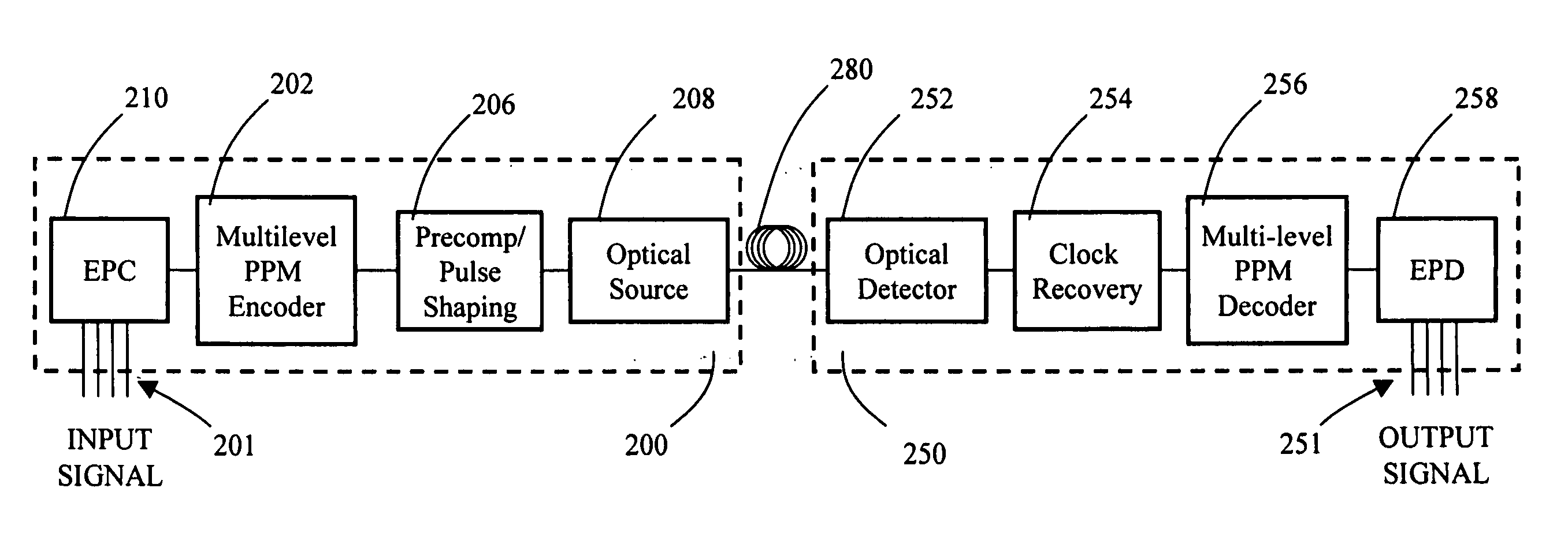
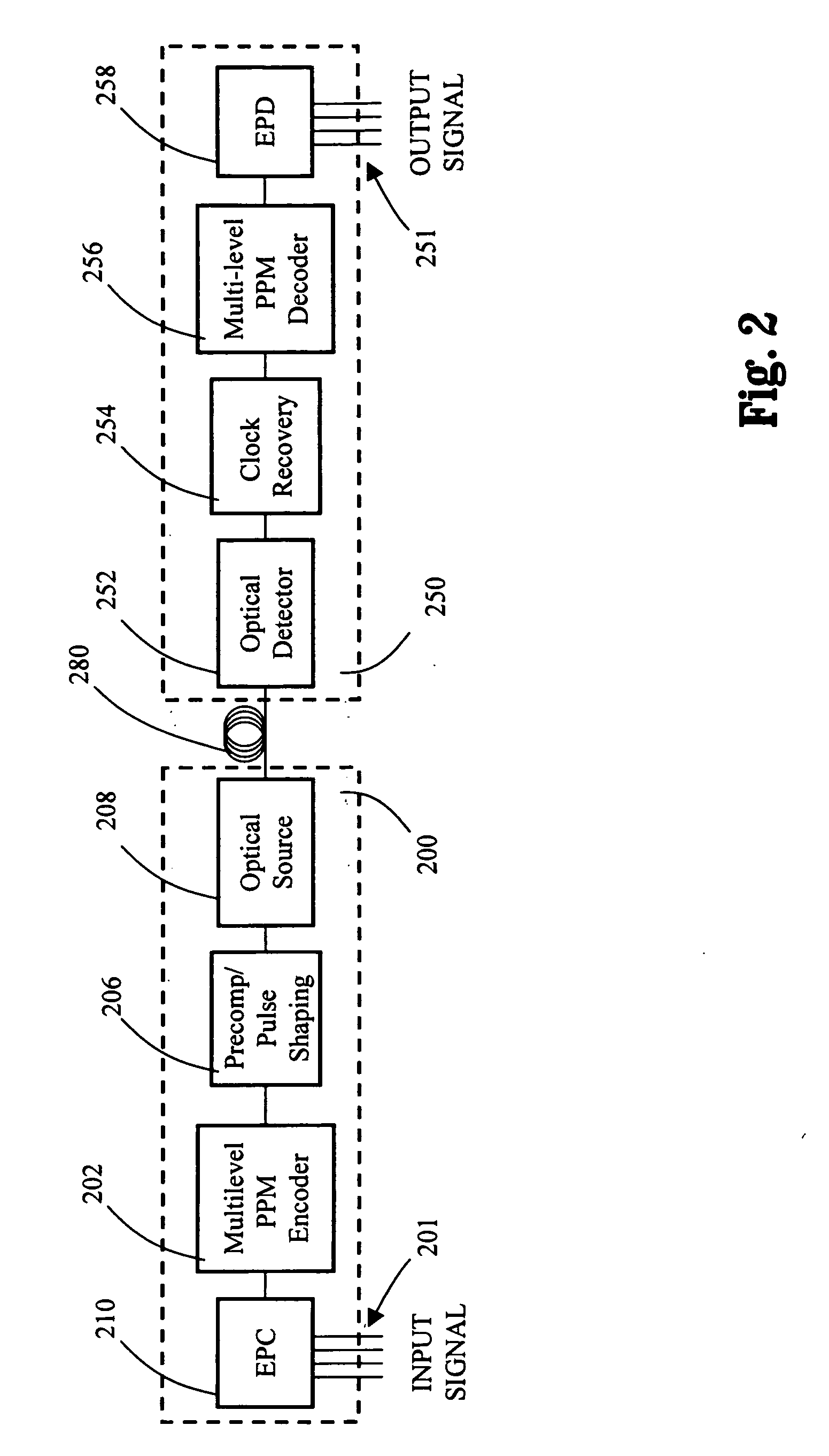
[0030] In an exemplary embodiment of the present invention, the average transmitted power in an optical fiber communication channel is decreased by using multilevel amplitude modulation in conjunction with Pulse Position Modulation (PPM). This multilevel PPM does not entail any tradeoff between decreased power per channel and channel bandwidth and, therefore, enables a lower average transmitted power compared to On / Off Keying (OOK) with no reduction in aggregate data rate. Accordingly, multilevel PPM can be used in high-speed Dense Wavelength Division Multiplexed (DWDM) optical communication systems where the maximum number of channels has traditionally been limited by nonlinear effects associated with WDM transmission through optical fiber. This modulation technique can enable an increased number of channels in DWDM systems, thereby increasing aggregate data rates within those systems.

[0031]FIG. 2 is a block diagram depicting an exemplary operating environment in which an exemplar...


PUM


Abstract

Decreasing the average transmitted power in an optical fiber communication channel using multilevel amplitude modulation in conjunction with Pulse Position Modulation (PPM). This multilevel PPM method does not entail any tradeoff between decreased power per channel and channel bandwidth, enabling a lower average transmitted power compared to On / Off Keying (OOK) with no reduction in aggregate data rate. Therefore, multilevel PPM can be used in high-speed Dense Wavelength Division Multiplexed (DWDM) systems where the maximum number of channels is traditionally limited by nonlinear effects such as self-phase modulation (SPM), cross-phase modulation (XPM), four-wave mixing (FWM), stimulated Brillouin scattering (SBS), and stimulated Raman scattering (SRS). This modulation technique can enable an increased number of channels in DWDM systems, thereby increasing aggregate data rates within those systems.

Description

PRIORITY AND RELATED APPLICATIONS [0001] The present application claims priority to provisional patent application entitled, “Multilevel Pulse Position Modulation For Efficient Fiber-Optic Communication,” filed on Mar. 29, 2001 and assigned U.S. Patent Application Ser. No. 60 / 279,655.FIELD OF THE INVENTION [0002] The present invention relates to optical fiber communication systems and more particularly relates to decreasing the transmitted power of signal transmission over an optical fiber communication channel, while maintaining channel bandwidth, through the use of multilevel pulse position modulation. BACKGROUND OF THE INVENTION [0003] In virtually all fields of communications, there exists a persistent demand to transmit more data in less time. The amount of information that can be transmitted over a communications system (or through a component of that system) is referred to as the bit rate or the data throughput of the system. Traditionally, system throughput is increased by e...

Claims


Application Information

Patent Timeline
Patent Type & Authority Applications(United States)
IPC IPC(8): H04B10/04H04B10/155H04L25/49
CPCH04B10/5161H04B10/524H04B10/541H04L25/4902H04L25/4917
Inventor VRAZEL, MICHAEL G.RALPH, STEPHEN E.HIETALA, VINCENT MARK
Owner INTERSIL INC
Learn More