
Method and device for demolding

a technology of demolding and demolding plate, which is applied in the field of demolding plate, can solve the problems of inability to mass-produce the aforesaid devices, inconvenient application of nano-fabrication techniques, and inability to apply the current nano-imprint process to mass-produce the devices, etc., and achieve the effect of removing the adhesion force and separating from the substrate smoothly

Inactive Publication Date: 2007-04-26
IND TECH RES INST
View PDF6 Cites 31 Cited by
  • Summary
  • Abstract
  • Description
  • Claims
  • Application Information

AI Technical Summary

Benefits of technology

[0010] In view of the disadvantages of prior art, the primary object of the present invention is to provide an uncomplicated demolding device capable of effortlessly eliminating the adhesion force of vacuum effect exerting between a mold and a substrate during an imprinting process so as to enable the mold to be separated from the substrate smoothly.
[0016] Preferably, the vibration actuator is able to output a signal with non-specific frequency for enabling the vibration of the blade to be applicable for various imprinting processes.

Problems solved by technology

However, although the above focusing had led to the generating of many nano-fabrication techniques, most of which are costly and slow to process that they are not suitable to be applied for mass production.
However, the current nanoimprint process still can not be applied to mass-produce the aforesaid devices since the yield of any product mass-produced by the current nanoimprint process is poor, whereas the poor yield is caused by improper demolding that damages the imprinted microstructures or cause the polymer of the resist to adhere onto the mold.
Moreover, the improper demolding may be caused by the high aspect ratio of the pattern to be imprinted, the shrinkage of the resist, the vacuum generated between the mold and the imprinted resist, the factor of friction / viscosity, and so on.
However, the positioning of the feed ducts on the stamping mold will adversely affect the designs of pattern capable of being formed on the stamping tool, and thus the effective area of the resulting imprinted product is also affected.
However, the pulling of the extending portion of the tap not only can adversely affect the effective area of the resulting imprinted product, but also will quality of imprinted patterns formed adjacent to the tap.
However, the demolding mechanism disclosed above is too complicated to be used for demolding in a nanoimprint process whereas the mold and the substrate are almost of the same size.
However, the demolding requires a specific shape memory alloy designed to cope with the temperature change in the imprinting process, and it also requires a proper block to restrain the substrate, because of which the imprint process is complicated.
Moreover, the disposition of those complicated demolding devices usually will cause damage to the effective area of the imprinting and quality thereof.

Method used


Image

  • Method and device for demolding
  • Method and device for demolding
  • Method and device for demolding

Examples


Embodiment Construction

[0024] For your esteemed members of reviewing committee to further understand and recognize the fulfilled functions and structural characteristics of the invention, several preferable embodiments cooperating with detailed description are presented as the follows.

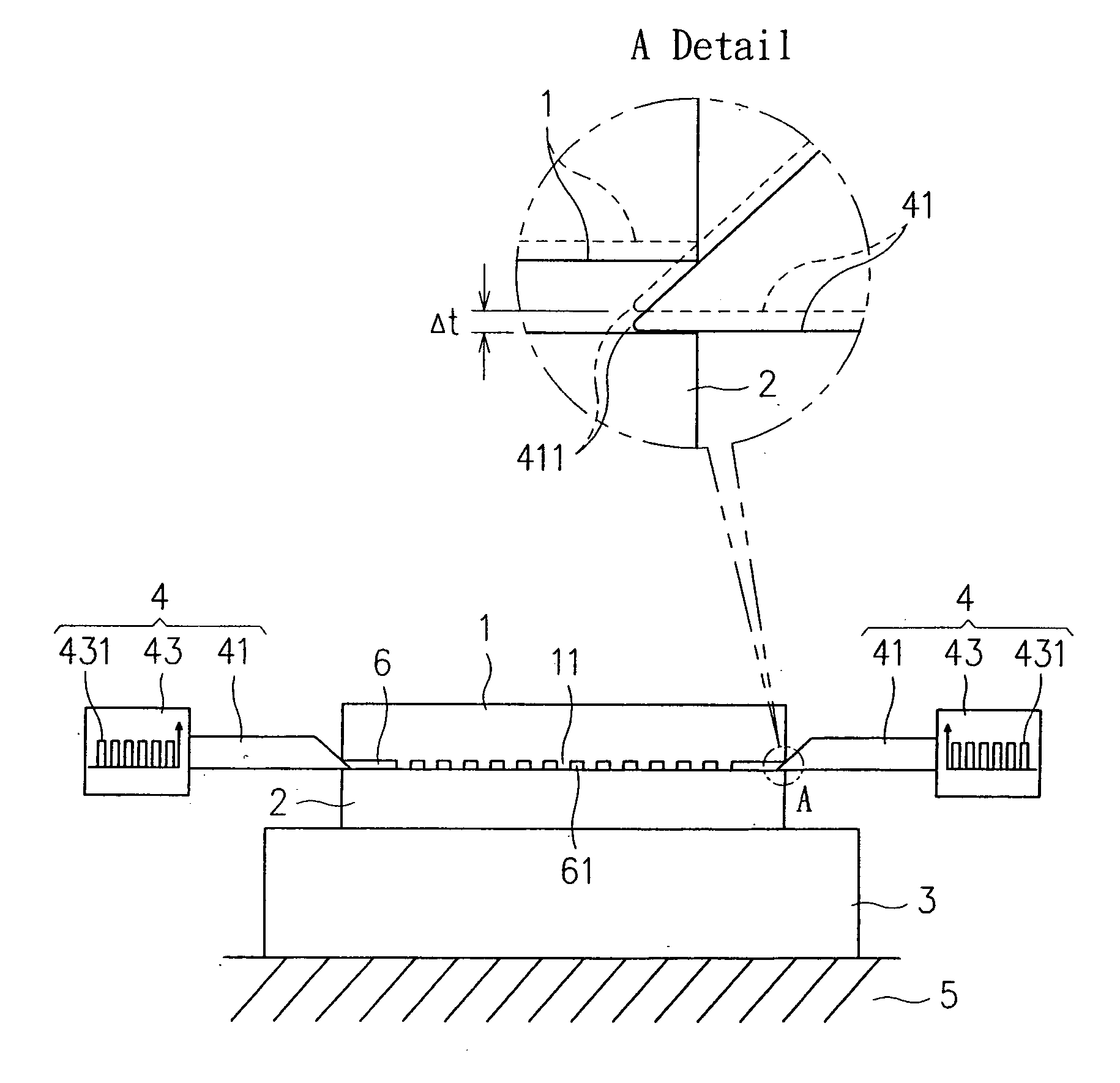
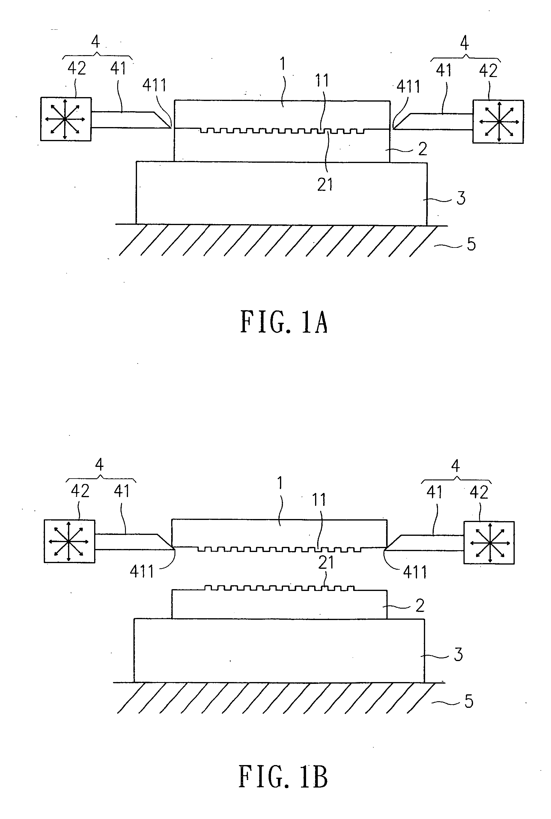
[0025] Please refer to FIG. 1A and FIG. 1B, which are schematic views of a demolding device according to a first embodiment of the invention. The demolding device shown in FIG. 1A and FIG. 1B primarily comprises a mold 1, a substrate 2, a supporting plate 3 and at least a blade module 4, wherein at least an assembly of patterns 11 is formed on a surface of the mold 1, whereas the feature size of patterns of the assembly 11, being used in a nanoimprint process, can be below 100 μm; and the substrate 2, substantially being a resist or a substrate having a layer of resist disposed thereon, is used to be pressed by the mold 1 for duplicating the patterns on the resist after the mold 1 is removed therefrom, and the resist is mad...


PUM

PropertyMeasurementUnit
Sizeaaaaaaaaaa
Forceaaaaaaaaaa
Degree of freedomaaaaaaaaaa

Abstract

The present invention relates to a demolding method and device, being used for detaching a mold and a substrate after completing an imprinting process, in which the mold is forced to detach from the substrate partially and form a gap therebetween by inserting at least a blade module between the two, and thus, as air is sucked into the gap and the adhesion force of vacuum effect exerting between the mold and the substrate is eliminated, the blade module is further applied to detach the mold from the substrate completely.

Description

FIELD OF THE INVENTION [0001] The present invention relates to a method and device for demolding, and more particularly, to an uncomplicated demolding device and method for separating a mold from a substrate effortlessly. BACKGROUND OF THE INVENTION [0002] In response to the trend of designing lighter, thinner, and smaller products, more and more related techniques for manufacturing miniature-sized device have becoming available. With respect to the overall advance of manufacturing process, both the top-down process and the bottom-up process are focusing on the development of producing nano-scaled devices. However, although the above focusing had led to the generating of many nano-fabrication techniques, most of which are costly and slow to process that they are not suitable to be applied for mass production. [0003] Take the nanoimprint process for instance, it is a mechanical replication technology for the fabrication of micro- and nanostructures that is similar to photolithography...

Claims


Application Information

Patent Timeline
IPC IPC(8): B29C45/40B81C99/00
CPCB29C33/44B29C37/0007B29C43/003B29C43/021B29C43/40B29C43/50B29C59/022B29C2043/025B29C2043/5038B29C2043/5069B29C2059/023
Inventor HO, YU-LUNWU, JEN-HUAWANG, WEI-HANCHEN, SHOU-RENCHEN, LAI-SHENG
Owner IND TECH RES INST
Features
  • Generate Ideas
  • Intellectual Property
  • Life Sciences
  • Materials
  • Tech Scout
  • Unparalleled Data Quality
  • Higher Quality Content
  • 60% Fewer Hallucinations
Learn More