Production method for polarization inversion unit

a production method and technology of polarization inversion, applied in the direction of instruments, optical elements, optics, etc., can solve the problems of periodic deterioration and unsatisfactory second harmonic wave generation efficiency

Active Publication Date: 2007-04-26
NGK INSULATORS LTD +1
View PDF4 Cites 0 Cited by
  • Summary
  • Abstract
  • Description
  • Claims
  • Application Information

AI Technical Summary

Benefits of technology

[0008] Further, in the case that the period is larger than 4 μm, a deep inversion structure can be easily obtained. On the contrary, in a region where the period is 4 μm or smaller, adjacent inversion parts tend to be connected with each other to result in deteriorated periodicity where deeper inversion structure is formed. As a result, the wavelength conversion rate may be lowered.
[0014] Specifically, the polarization inversion parts extending from the respective conductive portions tend to be connected with each other and periodic polarization inversion structure of a shorter period can be easily formed, by lowering the average length of the conductive portions to 9 μm or smaller. For example it could be successfully obtained a deeper periodic polarization inversion structure at a shorter period, such as 1.8 μm or 1.3 μm, which had not been obtained according to a prior process. On the viewpoint, the average length of the conductive portions may more preferably be 5 μm or smaller.
[0016] Further, the inventors have found the following. When a plurality of conductive films separated from each other are provided for forming a comb electrode, the length “db” of the conductive portion at the tip end of the electrode portion is made smaller than the length “da” of the conductive portion nearest to the base portion. The polarization inversion parts extending from the respective conductive portions thereby tend to be connected with each other and periodic polarization inversion structure of a shorter period can be easily formed.
[0018] Further, the inventors have found the following. When a plurality of conductive films separated from each other are provided for forming a comb electrode, the gap between the adjacent conductive portions are made 0.5 μm or larger and 5 μm or smaller. The polarization inversion parts extending from the respective conductive portions thereby tend to be connected with each other and periodic polarization inversion structure of a shorter period can be easily formed.

Problems solved by technology

However, a predetermined gap is provided between the tip end of the electrode piece of the comb electrode and each low resistance portion, and gaps are further provided between the adjacent low resistance portions.
It is thus considered that the efficiency of the second harmonic wave generation is not particularly improved.
On the contrary, in a region where the period is 4 μm or smaller, adjacent inversion parts tend to be connected with each other to result in deteriorated periodicity where deeper inversion structure is formed.

Method used


Image

  • Production method for polarization inversion unit
  • Production method for polarization inversion unit
  • Production method for polarization inversion unit

Examples


examples

(Experiment “A” According to the First and Third Aspect of the Invention)

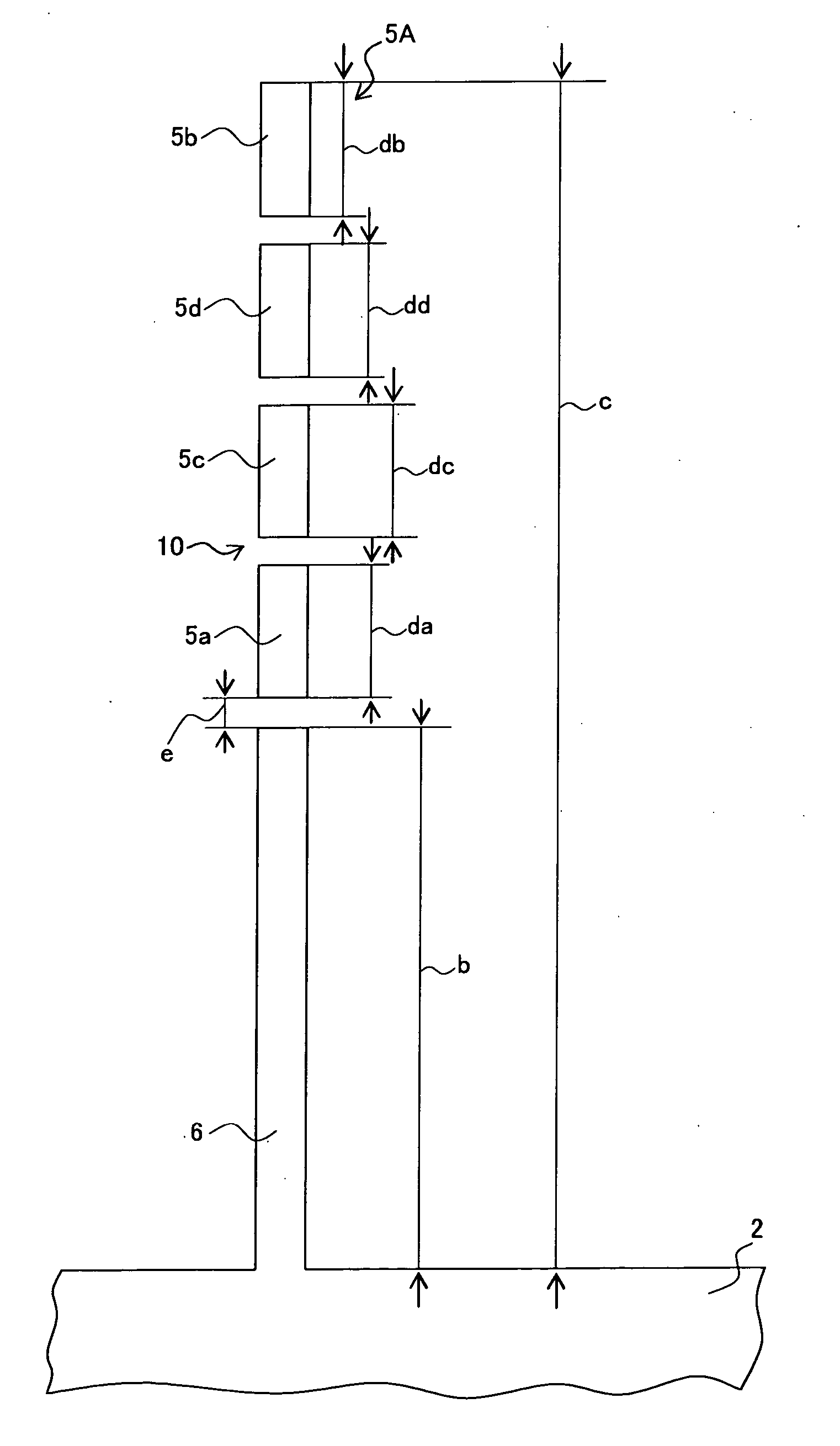
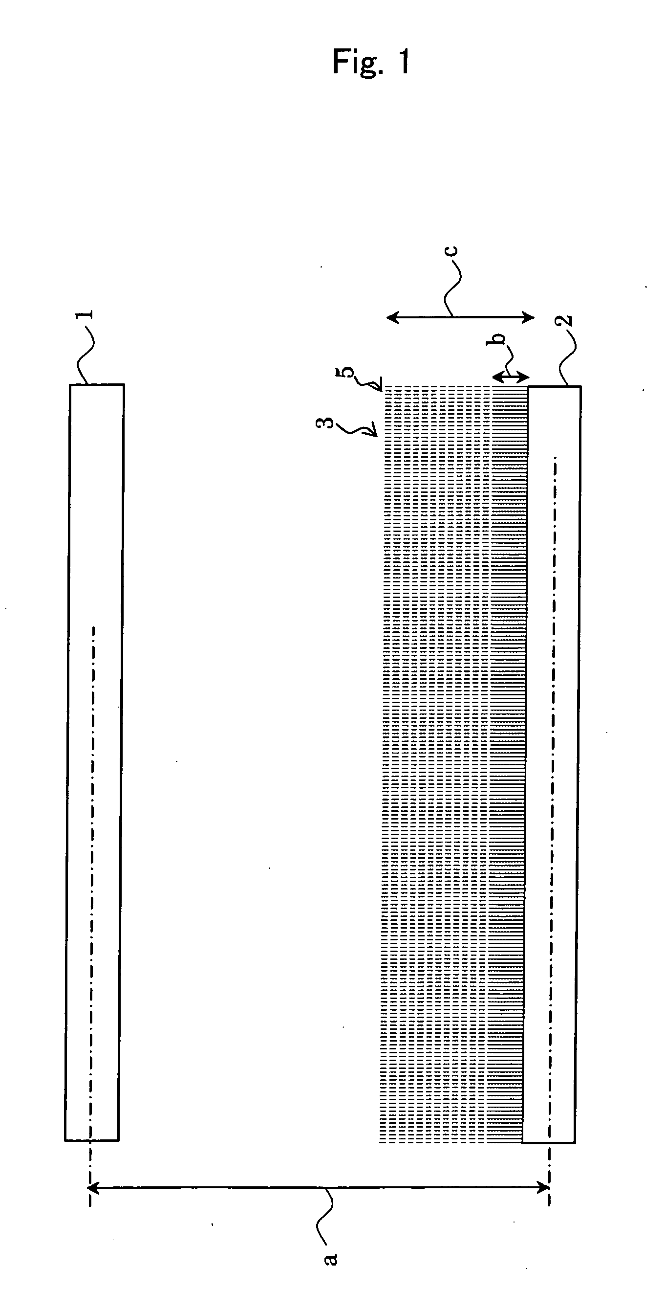
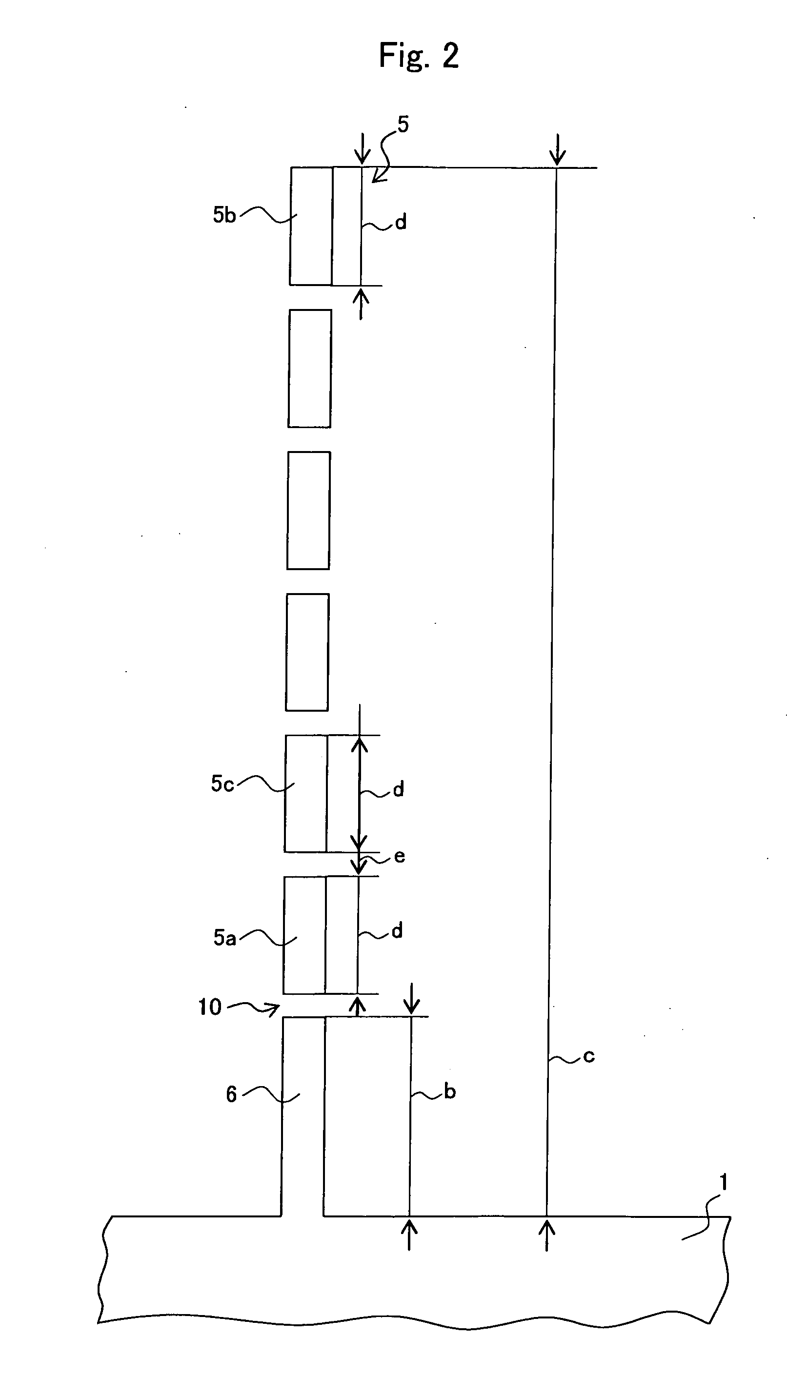
[0052] Periodic polarization inversion structure was formed by electric field polling process, according to the process described referring to FIGS. 1 to 3. The dimension “e” of the gap 10 of the conductive portions was made 10 μm, and the length of each of the conductive portions 5a, 5b and 5c was made 8 μm. The base portion 6 longer than the conductive portion was provided at the root of the electrode portion 5 for facilitating the electric supply to the electrode piece. The distance “a” between the centers of the opposing electrode 1 and supply electrode 2 was made 400 μm. The length “b” of the base portion 6 was 33 μm.

[0053] According to Experiment “A1”, the period of the periodic domain inversion was 1.8 μm. 13 conductive portions 5a, 5b and 5c were arranged each having a length “d” of 8 μm. The periodic polarization inversion structure was experimentally produced and tested as described above. The whol...


PUM

PropertyMeasurementUnit
lengthaaaaaaaaaa
lengthaaaaaaaaaa
lengthaaaaaaaaaa

Abstract

It is provided a novel method of producing polarization inversion parts by electric field polling process wherein the polarization inversion part extends to a deeper point from the surface of a substrate. The polarization inversion part is produced by electric field polling process using a comb electrode having a plurality of electrode portions 5 and a feeding portion 1. Each electrode portion 5 has a base portion 6 extending from the feeding portion 1 and a plurality of conductive portions 5a, 5b and 5c separated from the base portions 6, and the conductive portions have an average length “d” of 4 μm or longer and 9 μm or shorter. Alternatively, each electrode portion 5 has a base portion 6 extending from the feeding portion 1 and a plurality of conductive portions 5a, 5b and 5c separated from the base portion 6, and the conductive portion 5b at the tip end of the electrode portion has a length “db” smaller than the length “da” of the conductive portion 5b nearest to the base portion.

Description

BACKGROUND OF THE INVENTION [0001] 1. Field of the Invention [0002] The invention relates to a method of producing polarization inversion parts by means of electric field poling process. [0003] 2. Related Art Statement [0004] A second harmonic generation device based on quasi-phase-matching system has a ferroelectric single crystal, such as lithium niobate or lithium tantalite single crystal, with periodic polarization inversion structure formed therein. The device can generate light of relatively optional wavelength in a range from ultraviolet to infrared ray. Such device can be applied in various fields including an optical disk memory, medical, opto-chemical and various kinds of optical measurement uses. [0005] It is necessary to form deep polarization inversion structure in a ferroelectric single crystal, for attaining a high conversion efficiency in a second harmonic wave generation device. According to the method described in Japanese Patent publication No. H11-72809A, the sur...

Claims


Application Information

Patent Timeline
Patent Type & Authority Applications(United States)
IPC IPC(8): H01L21/00H01L29/94H01L27/108H01L29/76H01L31/119G02F1/355G02F1/37
CPCG02F1/3558G02F1/37
Inventor YAMAGUCHI, SHOICHIROIWATA, YUICHISUZUKI, KENGO
Owner NGK INSULATORS LTD
Why Eureka
Try Eureka