

Method for checking printability of a lithography target
a lithography target and printability technology, applied in the field of integrated circuit fabrication, can solve the problems of increasing the chip size and the process can waste precious design tim
- Summary
- Abstract
- Description
- Claims
- Application Information
AI Technical Summary
Benefits of technology
Problems solved by technology
Method used
Image

Examples
Embodiment Construction
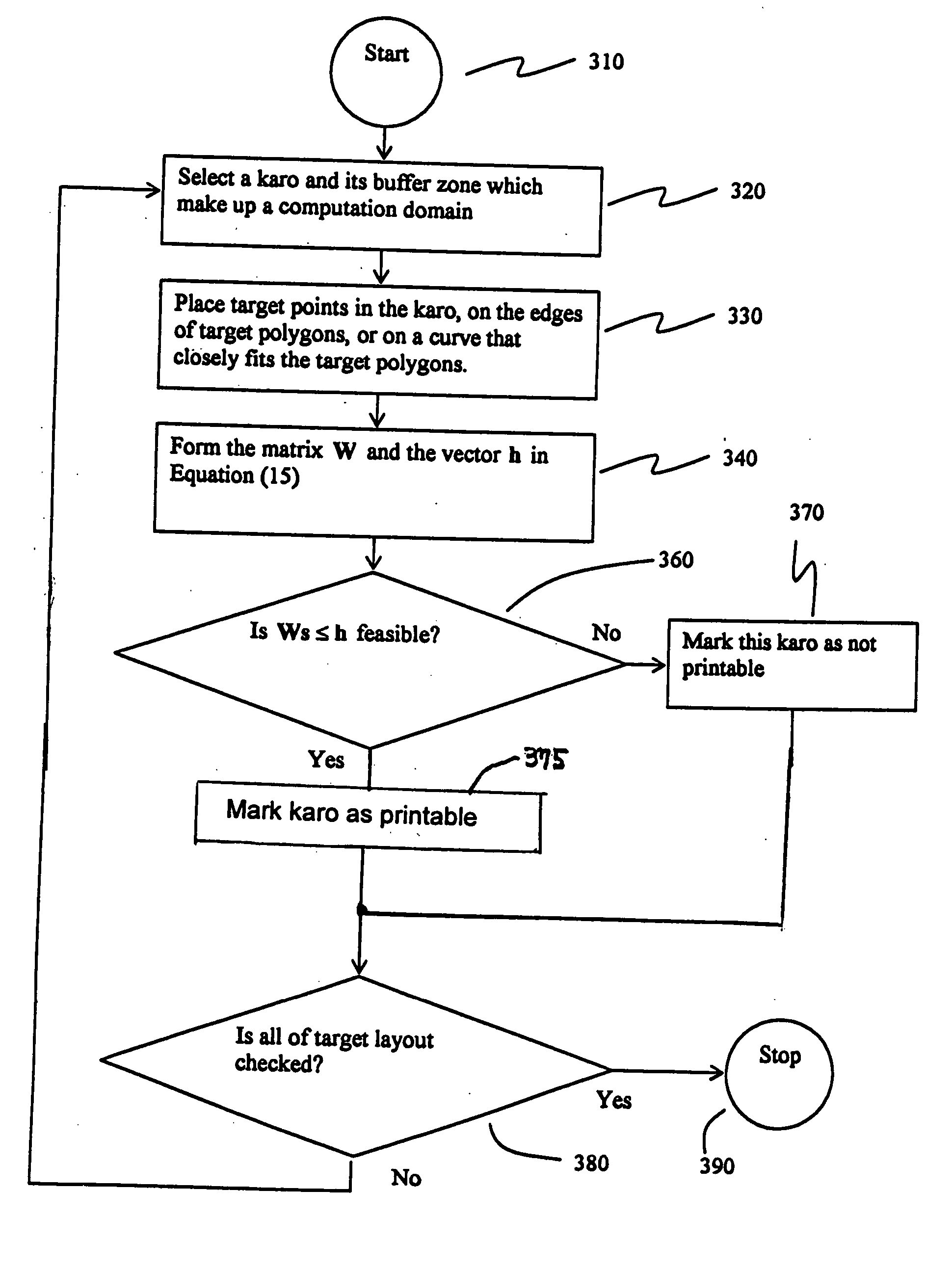
[0024] The terms “karo”, “target points,” and “normal vectors” are used in the description, and will first be defined.
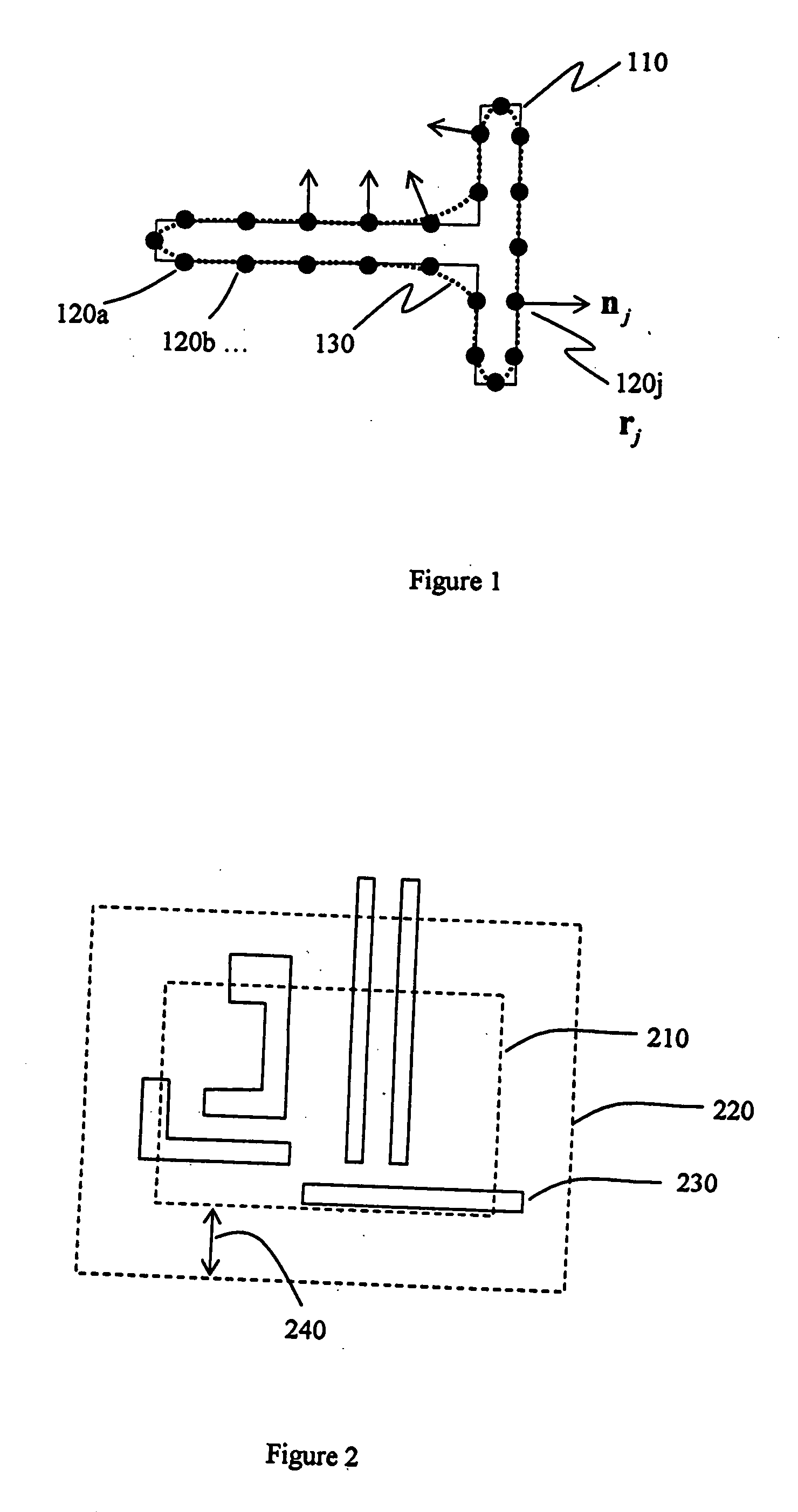
[0025] Techniques hereof check a small region of the target layer at a time. This region is called a karo. The union of karos cover the chip, or the part of the layout to be checked. Karos may overlap. Karos are rectangular in a preferred embodiment, although in alternative embodiments they can have any shape. The preferred size of a karo is between 0.5 and 2 micrometers for 193 nm exposure wavelength.
[0026] In a given karo, target points r1,r2, . . . , rM are selected on the edges of target polygons. The target points are used to help encapsulate the design requirements by a mathematical expression. In an embodiment hereof, target points on a polygon are approximately equally spaced by a distance of (kSAMPLE λ / NA), where kSAMPLE is a dimensionless factor that is less than 0.25 and preferably larger than 0.1; λ is the exposure wavelength, and NA is the numerical ap...
PUM
 Abstract
Description
Claims
Application Information