Solid state detector module structure and radiation imaging system

a detector module and detector module technology, applied in the field of solid-state detector module structure and radiation imaging system, can solve the problems of reducing the space resolution of the detection system, affecting the definition of imaging, and limiting the enhancement frequency of the accelerator, so as to improve the inspection speed, and improve the inspection speed of the radiation imaging inspection system

Active Publication Date: 2007-05-03
TSINGHUA UNIV +1
View PDF2 Cites 40 Cited by
  • Summary
  • Abstract
  • Description
  • Claims
  • Application Information

AI Technical Summary

Benefits of technology

[0016] By the aforementioned configuration of the present invention, it is convenient for assembling and disassembling the circuit board in the casing. And it is also the case for the connection of the detector plate with the front end circuit board as well as the fixing of the casing with the base plate. In addition, the inspection speed of the radiation imaging inspection system is greatly enhanced by adopting a double array solid state detector without decreasing the space resolution thereof. Since a collimator is provided at the front edge of the detector, it is possible to use a collimator with materials of different length for ray with different energy, and the damage to an optoelectronic diode as well as the scattering of the ray beams is decreased. And since the front end circuit board is not provided at a beam flow plane of the rays, the radiation to the circuit at the front of the rays is also decreased, enhancing the life span of the detector module. The solid state detector module structure of present invention decreases the scattering of ray beams, increases the capabilities of scattering resistance and the definition of image, and enhances inspection speed compared with prior art. And it is advantageous for an application of a radiation inspection system with high energy X rays which does not have a rear collimator.

Problems solved by technology

However, in real application, there is a limit for the enhancement of the frequency of the accelerator.
And arbitrary increase of the dimension of the detectors may decrease the space resolution of the detection system, affecting the definition of imaging.

Method used


Image

  • Solid state detector module structure and radiation imaging system
  • Solid state detector module structure and radiation imaging system
  • Solid state detector module structure and radiation imaging system

Examples


Embodiment Construction

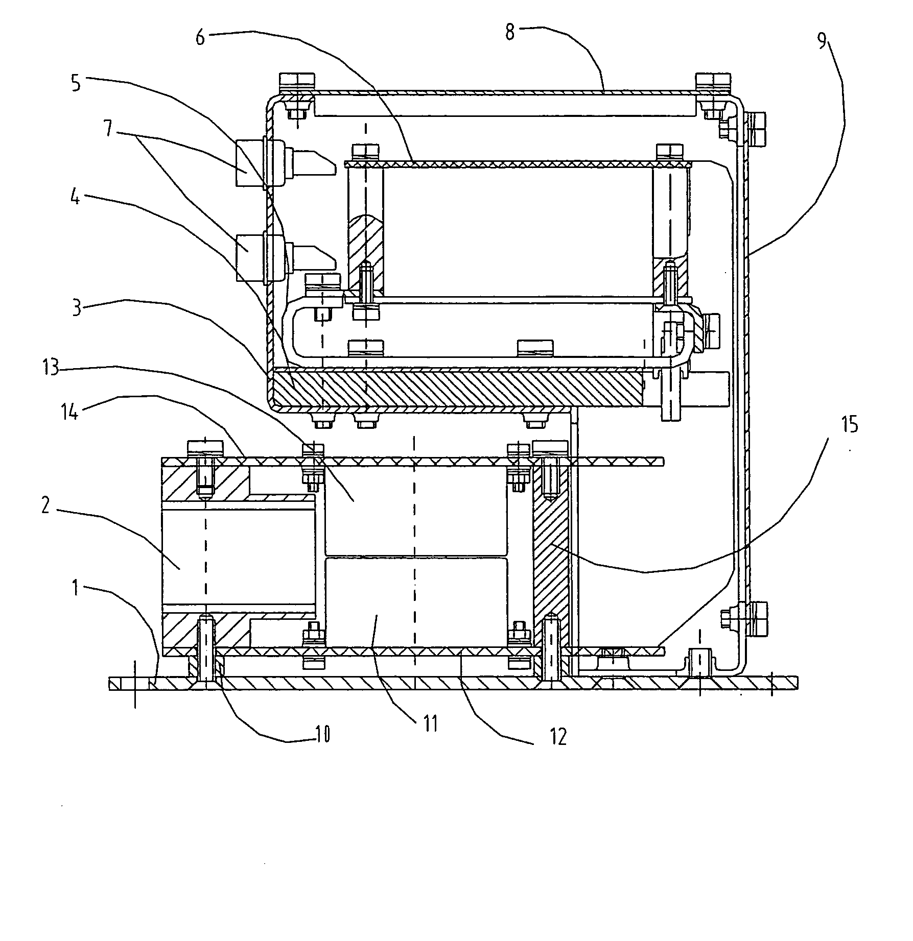
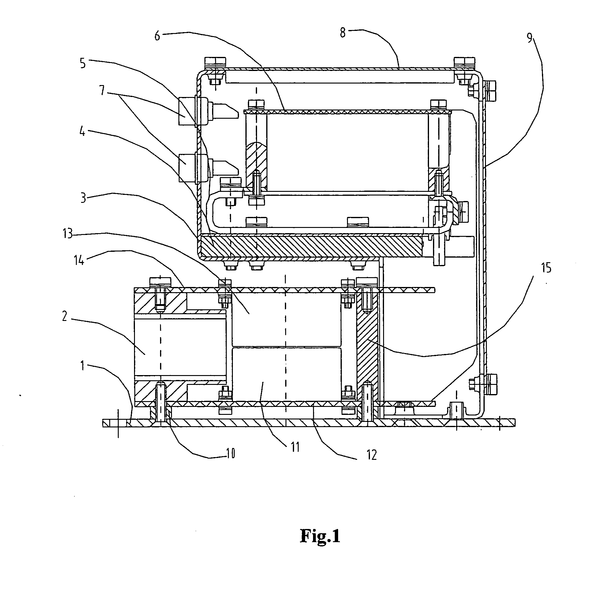
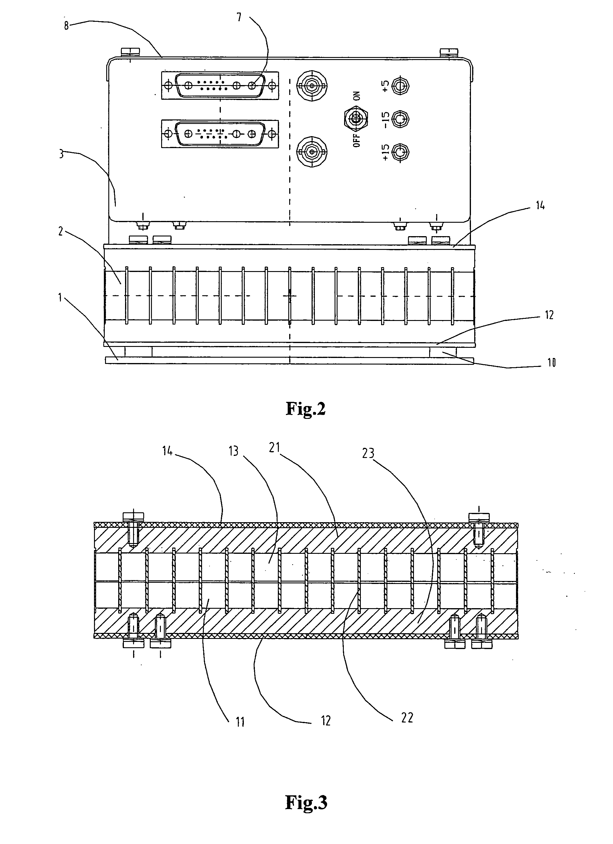
[0023] Reference will now be made in detail to the present preferred embodiments of the present invention, examples of which are illustrated in the accompanying drawings, wherein like reference numerals refer to like elements throughout. The embodiments are described below in order to explain the present invention by referring to the figures.

[0024] The solid state detector module structure according to the present invention, referring to FIGS. 1-3, comprises an upper support plate 14 and a lower support plate 12 provided opposing to each other, a collimator 2 provided between the upper support plate 14 and the lower support plate 12 for collimating the incident rays and resisting scatter of incident light beams; and solid state detector arrays provided between the upper support plate 14 and the lower support plate 12 at the rear side of the collimator in the transmitting direction of the rays, preferably the front end edge of the solid state detector arrays being adjacent to the co...


PUM


Abstract

The present invention discloses a solid state detector module structure, comprising: an upper support plate and a lower support plate provided opposing to each other, a collimator provided between the upper support plate and the lower support plate for collimating the incident rays; and solid state detector arrays provided between the upper support plate and the lower support plate at the rear side of the collimator in the transmitting direction of the rays, wherein the solid state detector arrays comprises an upper and lower rows, with the upper row of the solid state detector array fixed under the upper support plate, and the lower row thereof fixed on the lower support plate. The present invention further discloses a radiation imaging system having the same. The solid state detector module structure of present invention decreases the scattering of ray beams, increases the capabilities of scattering resistance and the definition of image and enhances inspection speed compared with prior art.

Description

BACKGROUND OF THE INVENTION [0001] 1. Field of the Invention [0002] Various embodiments of the present invention relates to a solid state detector module structure and a radiation imaging system having the same. [0003] 2. Description of the Related Art [0004] Generally, a solid state detector module structure for radiation imaging in prior art has the advantages of small volume, easiness of assembly and maintenance, and less radiation of rays for circuits at front end etc.. However, there is still a need for the enhancement of inspection speed of an inspection system. For increasing the inspection speed in the inspection system, the dimensions of the detectors in the detector array are enlarged for single-array detectors, or the beam-exit frequency of an electron accelerator is increased for accelerating the inspection. However, in real application, there is a limit for the enhancement of the frequency of the accelerator. And arbitrary increase of the dimension of the detectors may ...

Claims


Application Information

Patent Timeline
Patent Type & Authority Applications(United States)
IPC IPC(8): G01T1/24
CPCG01T1/243A61B6/03G01N23/04G21K1/02G01T1/24
Inventor LI, YUANJINGZHANG, QINGJUNZHAO, SHUQINGDAI, ZHUDEJIANG, NIANMINGMIAO, QITIANLI, ZHIJUN
Owner TSINGHUA UNIV
Why Eureka
Try Eureka