Terminal box for centrifugal switch of motor and motor with the same

a technology of centrifugal switch and terminal box, which is applied in the direction of electrical apparatus construction details, instruments, and electrical apparatus casings/cabinets/drawers, etc., can solve the problems of difficult and inconvenient removal of electric connection sheets by users, and achieves convenient disassembly and assembly, simple structure, and great convenience for users

Active Publication Date: 2011-09-29
ZHONGSHAN BROAD OCEAN MOTOR MFG
View PDF5 Cites 2 Cited by
  • Summary
  • Abstract
  • Description
  • Claims
  • Application Information

AI Technical Summary

Benefits of technology

[0008]In a class of this embodiment, the wiring mechanism comprises a first connecting terminal, a second connecting terminal, and an electrical lead.
[0009]In a class of this embodiment, the first connecting terminal is connected to the connecting part, the second connecting terminal is connected to the terminal, one end of the electrical lead is connected to the first connecting terminal, and the other end thereof bypasses the outside of the separating plate and connected to the second connecting terminal.
[0011]Advantage of the invention comprises: the wiring mechanism features simple structure, and convenient disassembling and assembling, which brings great convenience for users of the motor; even the thermostat has temperature detection failure, the users can easily remove the wiring mechanism, and timely switch off the power supply connected to the motor via an external protection circuit, whereby preventing the motor from being burned out.
[0012]It is another objective of the invention to provide a motor that is capable of addressing the above-mentioned problems and comprising a wiring mechanism in a terminal box thereof, and features simple structure of a wiring mechanism, and convenient assembling and disassembling, brings great convenience for users of the motor, and prevents the motor from being burned out.
[0013]In accordance with another embodiment of the invention, provided is a motor, comprising a stator, a rotor, a front end cover, a rear end cover, and a terminal box, comprising a box comprising a receiving part, a movable control rod, multiple electric contacts, a thermostat having a terminal, and a wiring mechanism. The front end cover is connected to the rear end cover whereby forming a cavity, the rotor and the stator are disposed in the cavity, the terminal box is disposed on outer wall of one of the front end cover and the rear end cover, the movable control rod is disposed on the box and partially extends therefrom, the electric contacts are disposed in the box, the thermostat is disposed on end surface of the box, the receiving part operates to receive the thermostat, one end of the electric contact extends from the box and forms a connecting part, a separating plate is disposed between the connecting part and the thermostat, one end of the wiring mechanism is connected to the connecting part, and the other end thereof bypasses the outside of the separating plate and is connected to the terminal.
[0014]In a class of this embodiment, a fixing part is disposed on outer wall of the end cover and in the vicinity of the terminal box, the fixing part comprises a fixing clamp, the fixing clamp fixes an enameled wire led out from the motor, and a tail of the enameled wire is disposed in the terminal box.

Problems solved by technology

This structure has the following problems: since the electric connection sheet is spot-welded with the terminal of the thermostat, as the thermostat has temperature detection failure, it is impossible to timely switch off the power supply connected to the motor, and the motor will be burned out, which brings great trouble for users of the motor.
Moreover, it is difficult and inconvenient for the users to remove the electric connection sheet.

Method used


Image

  • Terminal box for centrifugal switch of motor and motor with the same
  • Terminal box for centrifugal switch of motor and motor with the same
  • Terminal box for centrifugal switch of motor and motor with the same

Examples


example 1

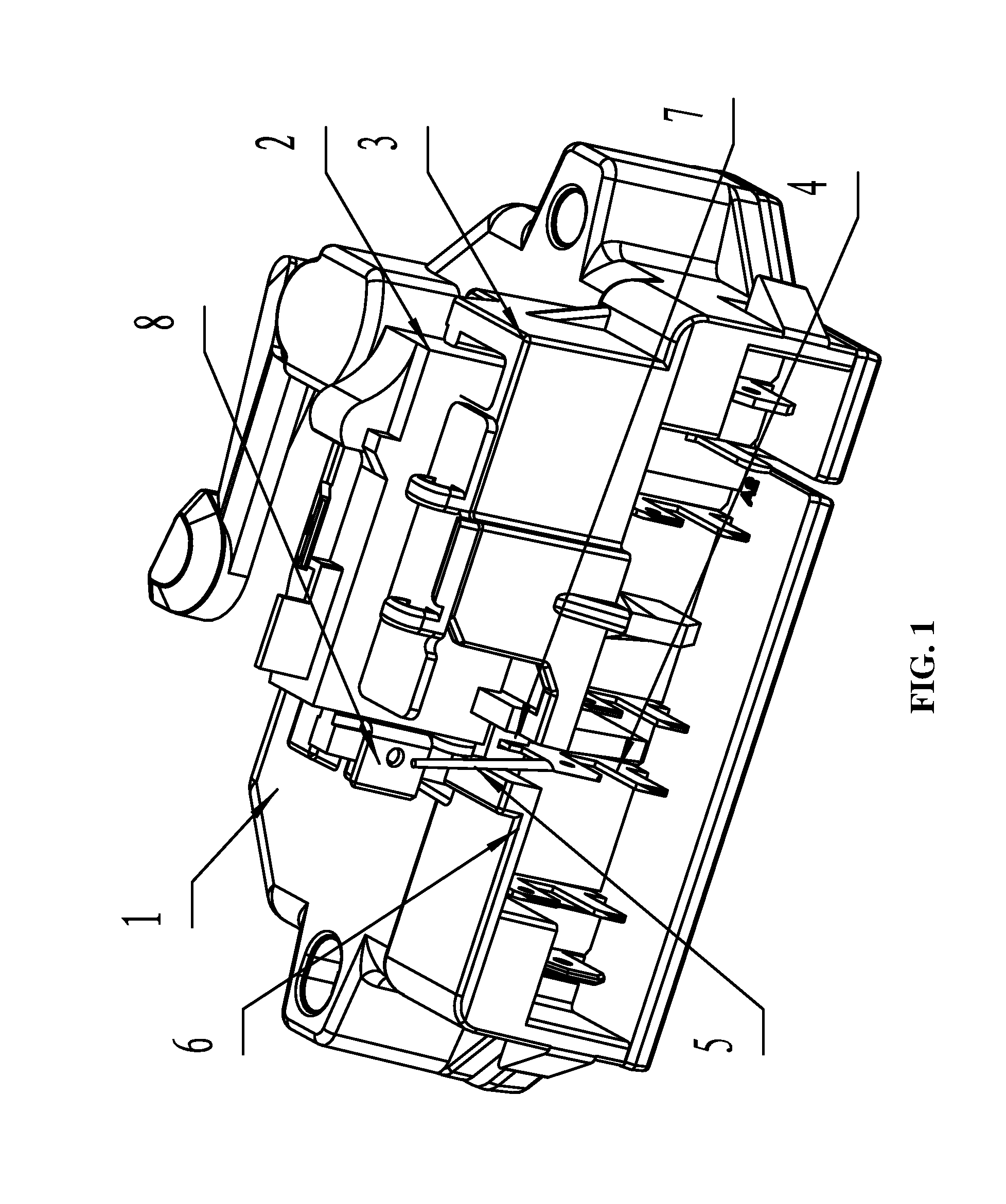
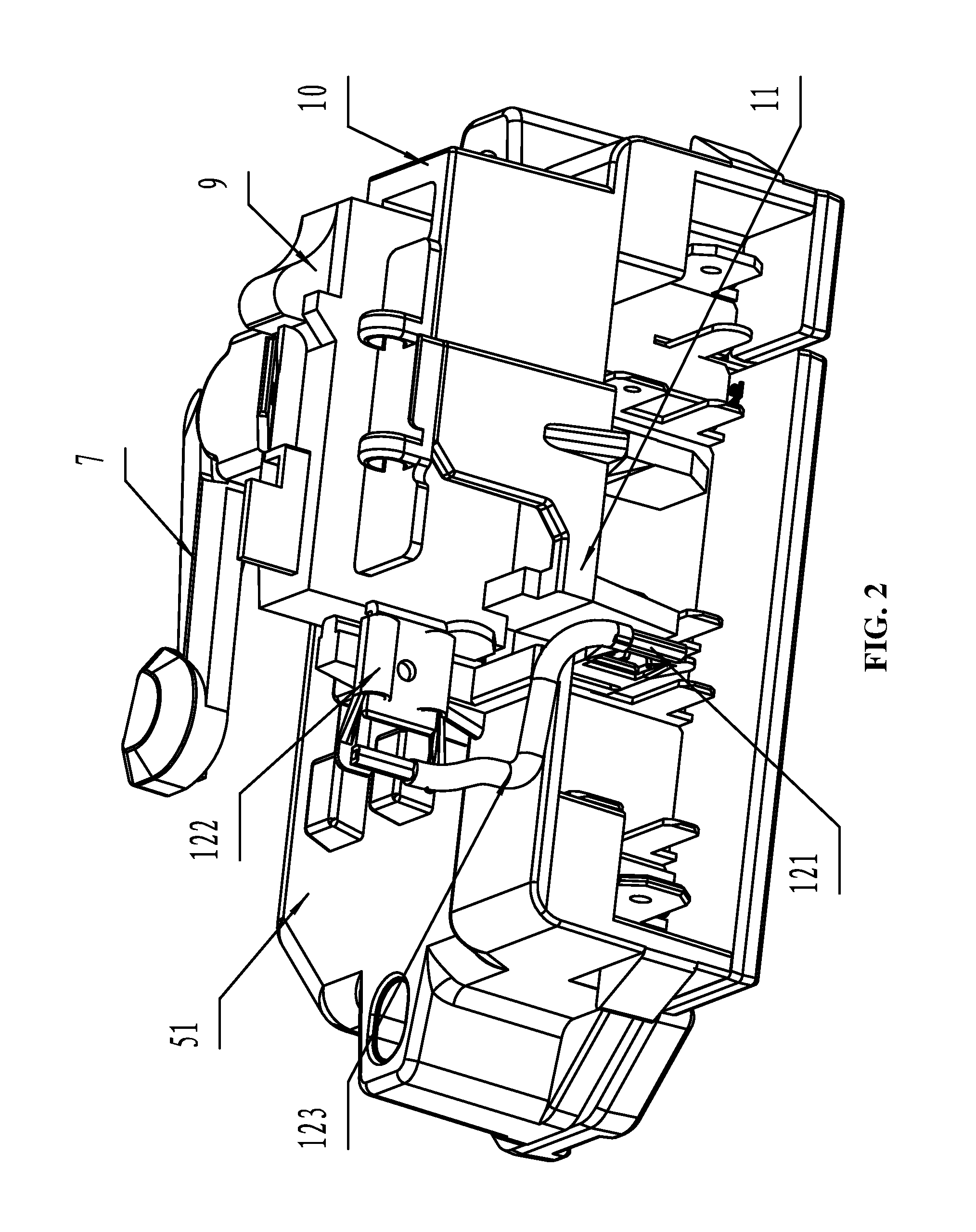
[0029]As shown in FIGS. 2, 3 and 4, a terminal box for a centrifugal switch of a motor comprises a box 51, a movable control rod 7 disposed on the box 51 and partially extending from the box, multiple electric contacts 8 disposed in the box 51, and a thermostat 9 disposed on end surface of the box. The box 51 comprises a receiving part 10 operating to receive the thermostat 9, one end of the electric contact 8 extending from the box and forming a connecting part 81, a separating plate 11 being disposed between the connecting part 81 and the thermostat 9. The terminal box further comprises a wiring mechanism 12, one end of the wiring mechanism 12 is connected to the connecting part 81, and the other end thereof bypasses the outside of the separating plate 11 and is connected to a terminal 91 of the thermostat 9.

[0030]The wiring mechanism 12 comprises a first connecting terminal 121 connected to the connecting part 81, a second connecting terminal 122 connected to the terminal 91, and...

example 2

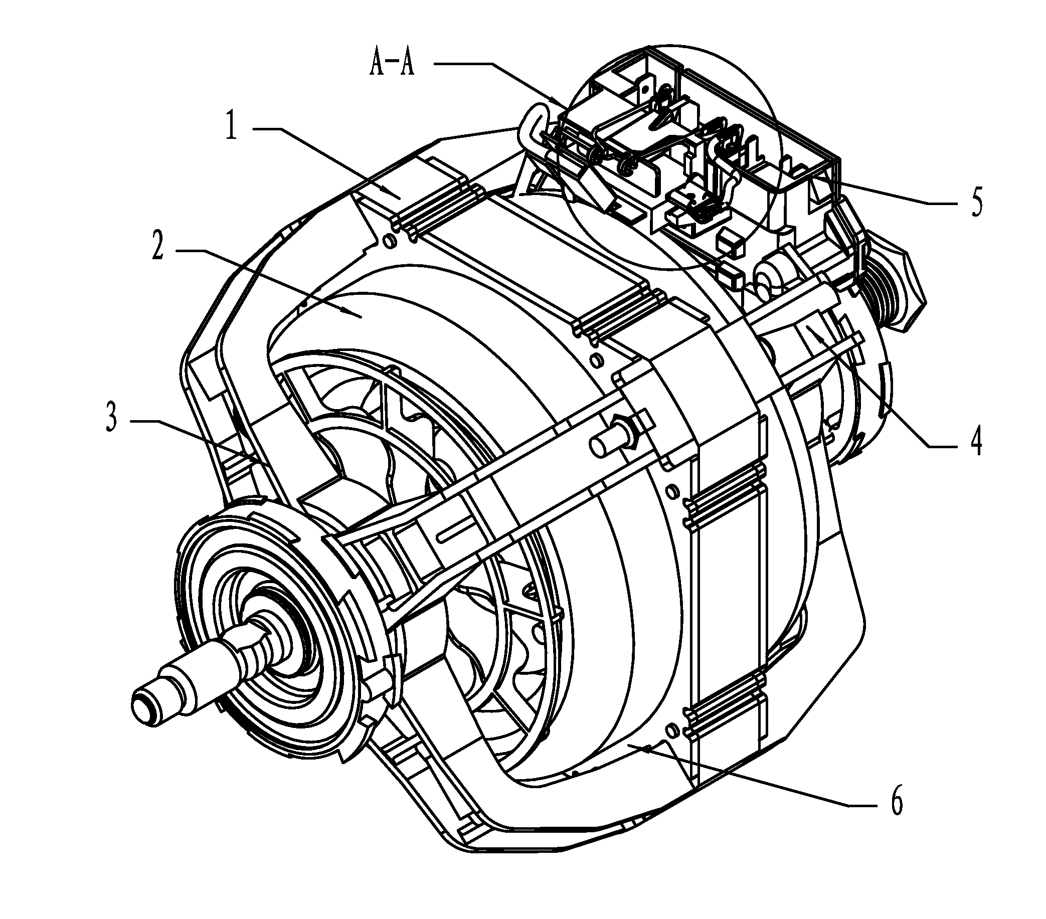
[0031]As shown in FIG. 7, a motor of the invention comprises a stator 1, a rotor 2, a front end cover 3, a rear end cover 4, and a terminal box 5. The front end cover 3 is connected to the rear end cover 4 whereby forming a cavity 6, the rotor 2 and the stator 1 is disposed in the cavity 6, the terminal box 5 is disposed on outer wall of one of the end covers. As shown in FIGS. 2, 3 and 4, the terminal box 5 comprises a box 51, a movable control rod 7 disposed on the box 51 and partially extending from the box, multiple electric contacts 8 disposed in the box 51, and a thermostat 9 disposed on end surface of the box. The box 51 comprises a receiving part 10 operating to receive the thermostat 9, one end of the electric contact 8 extending from the box and forming a connecting part 81, a separating plate 11 is disposed between the connecting part 81 and the thermostat 9. The terminal box further comprises a wiring mechanism 12, one end of the wiring mechanism 12 is connected to the c...


PUM


Abstract

A terminal box, including at least a box (51) having a receiving part (10), a movable control rod (7), multiple electric contacts (8), a thermostat (9) having a terminal (91), and a wiring mechanism (12). The movable control rod (7) is disposed on the box (51) and partially extends therefrom. The electric contacts (8) are disposed in the box (51). The thermostat (9) is disposed on end surface of the box (51). The receiving part (10) operates to receive the thermostat (9). One end of the electric contact (8) extends from the box (51) and forms a connecting part (81). A separating plate (11) is disposed between the connecting part (81) and the thermostat (9). One end of the wiring mechanism (12) is connected to the connecting part (81), and the other end thereof bypasses the outside of the separating plate (11) and is connected to the terminal (91). If the thermostat experiences temperature detection failure, users of the motor can easily remove the wiring mechanism, and timely switch off the power supply connected to the motor via an external protection circuit thereby preventing the motor from being burned out.

Description

CROSS-REFERENCE TO RELATED APPLICATIONS[0001]Pursuant to 35 U.S.C. §119 and the Paris Convention Treaty, this application claims the benefit of Chinese Patent Application No. 201020148430.5 filed on Mar. 25, 2010, the contents of which are incorporated herein by reference.BACKGROUND OF THE INVENTION[0002]1. Field of the Invention[0003]The invention relates to a terminal box for a centrifugal switch of a motor and a motor using the same.[0004]2. Description of the Related Art[0005]Nowadays, most terminal boxes for centrifugals switches of single-phase induction motors each comprise a box, a movable control rod extending from the box, and a thermostat disposed on end surface of the box. A function of the thermostat is to switch off a power supply connected to the motor as temperature is too high. As shown in FIG. 1, a box comprises a receiving part 3 operating to receive the thermostat 2, and multiple connecting terminals 4. An electric connection sheet 5 is extended from the top of t...

Claims


Application Information

Patent Timeline
Patent Type & Authority Applications(United States)
IPC IPC(8): H02K11/00H05K7/00
CPCH01H1/5866H01H35/10H02K11/0047H01H37/06H02K5/225H01H37/043H02K11/25
Inventor CHEN, FUCHENGLU, PINGDENG, SHUANGCHAOLIU, XIAO
Owner ZHONGSHAN BROAD OCEAN MOTOR MFG
Why Eureka
Try Eureka