Piezoelectric device

a technology of piezoelectric devices and piezoelectric devices, which is applied in piezoelectric/electrostrictive/magnetostrictive devices, microelectromechanical systems, piezoelectric/electrostrictive/magnetostriction machines, etc., can solve the problems of poor heat releasing properties, poor shielding properties of each configuration, and relatively long route lengths, etc., to improve the heat releasing properties and improve the shielding properties

Active Publication Date: 2007-05-03
MURATA MFG CO LTD
View PDF2 Cites 29 Cited by
  • Summary
  • Abstract
  • Description
  • Claims
  • Application Information

AI Technical Summary

Benefits of technology

[0029] The piezoelectric device of the present invention can improve the shielding property and, in addition, improve the heat releasing property.

Problems solved by technology

Each of these configurations has poor shielding properties.
Therefore, the route becomes relatively long, and the heat releasing property is poor.
Therefore, the distance between the heat generation portion and the mounting substrate is short.
However, since the arrangement of the external electrode is not taken into consideration, the heat releasing property to the mounting substrate is not always good.

Method used


Image

  • Piezoelectric device
  • Piezoelectric device
  • Piezoelectric device

Examples


Embodiment Construction

[0051] The embodiment of the present invention will be described below with reference to examples and FIG. 1 to FIG. 4.

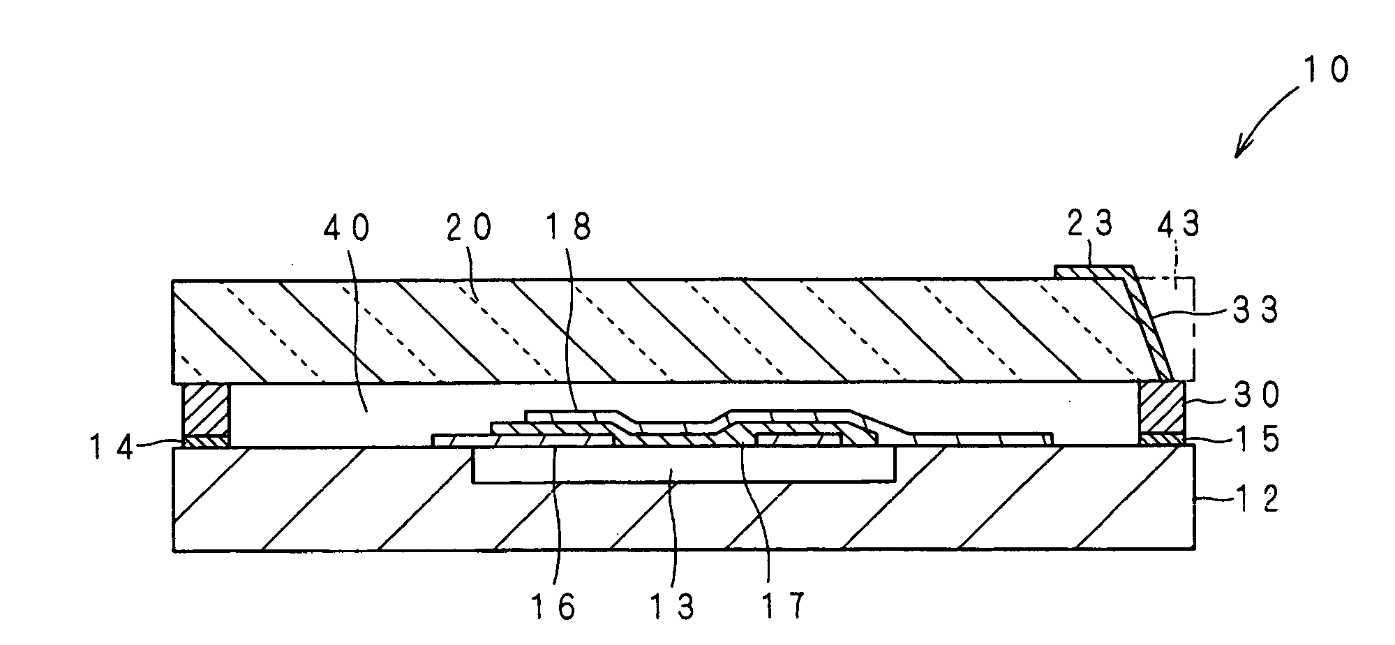
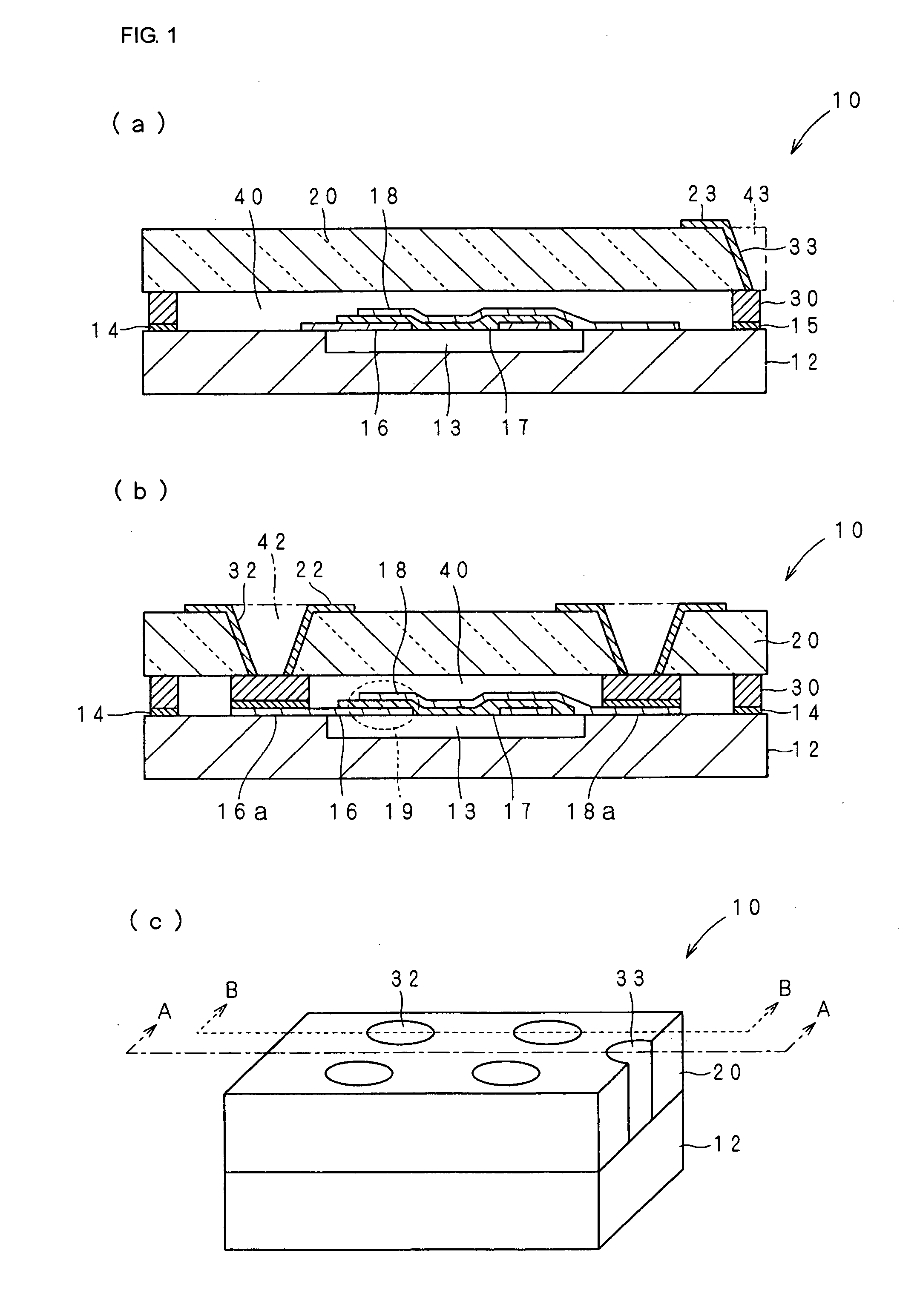
[0052] As indicated by an external view shown in FIG. 1 (c), a piezoelectric device 10 has a silicon substrate 12 provided with an element and a glass substrate 20 serving as a cover. The silicon substrate 12 and the glass substrate 20 are stacked and sealed.

[0053] As shown in FIG. 1 (a) and (b), which are sectional views taken along lines A-A and B-B shown in FIG. 1 (c), a hole 13 is disposed by removal with etching or the like in a surface of the silicon substrate 12 opposing to the glass substrate 20. A vibration portion 19, in which a piezoelectric thin film 17 is sandwiched between electrode films 16 and 18, is disposed on the hole 13. The vibration portion 19 floats in an internal space 40, and is acoustically separated. For example, Al electrode films 16 and 18 and an AlN piezoelectric thin film 17 are formed by evaporation or sputtering. The vibration port...


PUM


Abstract

A piezoelectric filter capable of improving the shielding property and increasing the heat releasing property is provided. The piezoelectric device includes a cover and piezoelectric device chips which are stacked and sealed together. The piezoelectric device also includes first external electrodes exposed at an upper surface of the cover and a grounded second external electrode exposed at the upper surface and a side surface of the cover. Electroconductive bonding materials are disposed between the cover and the piezoelectric device chips and all around an outer edge which connects the cover to the piezoelectric device chips so as to form a seal. The electroconductive bonding materials are also connected to the grounded second external electrode.

Description

CROSS REFERENCE TO RELATED APPLICATIONS [0001] The present application is a continuation of International Application No. PCT / JP 2005 / 008426, filed May 9, 2005, which claims priority to Japanese Patent Application No. JP 2004-188843, filed, Jun. 25, 2004, the entire contents of each of these applications being incorporated herein by reference in their entiretyFIELD OF THE INVENTION [0002] The present invention relates to a piezoelectric device provided with elements, e.g., a resonator and a filter, including piezoelectric thin films. BACKGROUND OF THE INVENTION [0003] In order to miniaturize piezoelectric devices, e.g., piezoelectric thin film filters (BAW filters) and surface acoustic wave filters (SAW filters), a CSP (chip size package), in which an element chip and a cover are sealed by a bonding layer formed along outer edges of their respective main surfaces, has been proposed previously (refer to, for example, Patent Documents 1 and 2). Patent Document 1: Japanese Unexamined ...

Claims


Application Information

Patent Timeline
Patent Type & Authority Applications(United States)
IPC IPC(8): H01L41/053
CPCB81B2201/0271H03H3/02H03H9/02086H03H9/105H03H9/173H03H9/10
Inventor FUJII, HIDETOSHITAKEUCHI, MASAKI
Owner MURATA MFG CO LTD
Why Eureka
Try Eureka