Electric power steering apparatus and controller therefor

a technology of electric power steering and controller, which is applied in the direction of electric motor control, dc motor speed/torque control, transportation and packaging, etc., can solve the problems of reducing the degree of freedom in the deign of the motor, impaired steering feeling, and impaired follow-up property of the motor with respect to a control command value, etc., to reduce the loss torque of the motor, and reduce the loss of iron. physical

Inactive Publication Date: 2007-05-03
NSK LTD
View PDF2 Cites 20 Cited by
  • Summary
  • Abstract
  • Description
  • Claims
  • Application Information

AI Technical Summary

Benefits of technology

[0057] According to the controller for an electric power steering apparatus of the invention, the friction compensation flux-weakening current is calculated as the friction compensation value for the motor, and the friction compensation flux-weakening current is added to the d-axis current command value which controls the flux strength to weaken the flux of the motor, whereby

Problems solved by technology

However, the target current value which is output as torque from the motor is corrected, and hence the correction value and cogging torque which are not offset because of an error are produced as vibration.
Even in the case where a vehicle travels at a high or medium speed and a steering wheel is slowly rotated, i.e., in the case where the driver perceptively feels the steering feeling, when the motor control is performed in the same manner as other cases, the cogging torque of the motor is transmitted as vibrations to the steering wheel, thereby causing a problem in that the steering feeling is impaired.
When a control in which the control gain is reduced so as to always eliminate influences of high-frequency noises and the like, or which involves complex calculations for eliminating pulsation torque is performed, there arises a problem in that the follow-up property of the motor with respect to a control command value is impaired.
Also in the case where cogging torque is reduced by the structure of a motor as in Japanese Patent Unexamined Publication JP-A-2003-250254, there is a problem in that the degree of freedom in the deign of the motor is largely reduced, for example, a motor which is f

Method used


Image

  • Electric power steering apparatus and controller therefor
  • Electric power steering apparatus and controller therefor
  • Electric power steering apparatus and controller therefor

Examples


first embodiment

[0071] At first, first and second embodiments relate to aspects of the invention in which a controller is provided with a cogging torque compensation value calculating portion is described.

[0072] Conventionally, reduction of cogging torque is performed by improving the structure of a motor as described in JP-A-2003-250254, or by performing correction so as to offset the torque with a target torque as described in JP-A-2005-67359. In the invention, by contrast, attention is focused on the principle of generation of cogging torque, and simple control logic can surely reduce the cogging torque without requiring addition of expensive hardware.

[0073] First, the principle of generation of cogging torque on which the invention is based will be described.

[0074] Usually, cogging torque is produced by a change of the magnetic energy in a gap in accordance with movement of a magnetic pole of a permanent magnet. The change of the magnetic energy is caused by a winding slot. When θ is the mov...

second embodiment

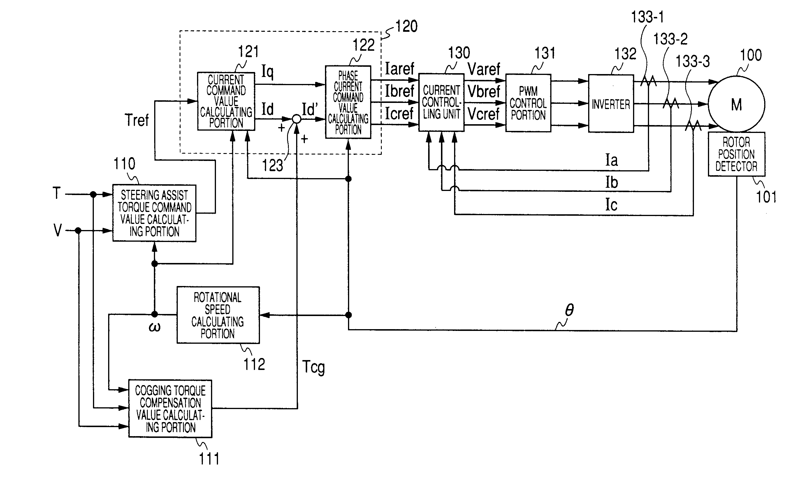
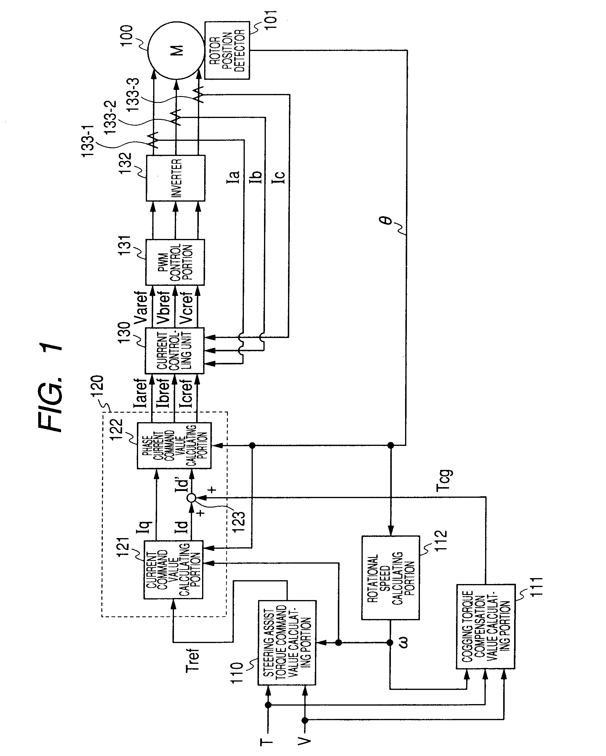
[0091]FIG. 4 shows a second embodiment of the invention in which a current-feedback is performed on the d-q axes. FIG. 4 is illustrated so as to correspond to FIG. 1. That is, the phase currents Ia, Ib, Ic from the current detectors 133-1, 133-2, 133-3 are converted to two-phase currents I1, I2 in a three to two-phase converter 135, and the current controlling unit 130 calculates two-phase voltage command values Vqref, Vdref. Namely, a current-feedback is performed on the d-q axes. The two-phase voltage command values Vqref, Vdref are supplied to a two to three-phase converter 134, and then converted to the three-phase voltage command values Varef, Vbref, Vcref based on the rotational angle θ. The operation after the voltage command values Varef, Vbref, Vcref is identical with that in FIG. 1.

[0092] Also in the current-feedback system on the d-q axes, the correction by the cogging torque compensation value calculating portion 111 can be similarly applied.

[0093] The operation in the...

third embodiment

[0098] Hereinafter, third embodiment of the invention will be described with reference to the accompanying drawings. In the embodiment of the invention, an example in which a three-phase brush-less motor is used as a steering assist motor will be described.

[0099]FIG. 8 shows a configuration example of the controller according to the invention. The three-phase brush-less motor 1100 is drive-controlled by the vector control. In the vector control, the q-axis which is a coordinate axis of a rotor magnet, and which controls torque, and the d-axis for controlling the flux strength are independently set, and currents respectively corresponding to the axes are controlled by the vector because the axes are in a 90-deg. relationship. In the invention, a friction compensation flux-weakening current If which is calculated based on the steering torque T, the vehicle speed V, and the rotational speed ω is added to a d-axis current command value Id for the vector control, thereby performing fric...


PUM


Abstract

There is provided a controller for an electric power steering apparatus having a motor which applies a steering assist force to a steering mechanism. The controller includes a torque command value calculating portion which calculates a torque command value based on steering torque generated in a steering shaft, and a vehicle speed and a current command value calculating portion which calculates a current command value for the motor based on the torque command value. The controller controls the motor based on the current command value. In the apparatus, the controller has a cogging torque compensation value calculating portion which calculates a cogging torque compensation value for the motor, and corrects the current command value based on the cogging torque compensation value.

Description

BACKGROUND OF THE INVENTION [0001] 1. Field of the Invention [0002] The present invention relates to an electric power steering apparatus which gives a steering assist force to a steering system of an automobile or a vehicle by driving a brush-less DC motor. [0003] Also, the invention relates to a controller for the apparatus, and more particularly to a high-performance electric power steering apparatus in which a cogging torque compensation value is added to a d-axis current command value to reduce the cogging torque of a motor, and also to a controller for the apparatus. [0004] In addition, the invention also relates to a controller for the apparatus, and more particularly to an electric power steering apparatus in which a friction compensation flux-weakening current that is a friction compensation value is added to a d-axis current command value to reduce friction of a steering, and also to a controller for the apparatus. [0005] 2. Description of the Background Art [0006] An elec...

Claims


Application Information

Patent Timeline
IPC IPC(8): H02P7/00
CPCB62D5/0472
Inventor ENDO, SHUJIKOBAYASHI, HIDEYUKI
Owner NSK LTD
Why Eureka
Try Eureka