Display device for irreversibly switching from a first state to a second state

a display device and irreversible switching technology, applied in the field of non-reversible display devices, can solve the problem of valueable information being lost, and achieve the effect of low activation energy consumption

Inactive Publication Date: 2007-05-03
3M INNOVATIVE PROPERTIES CO
View PDF14 Cites 0 Cited by
  • Summary
  • Abstract
  • Description
  • Claims
  • Application Information

AI Technical Summary

Benefits of technology

[0007] It is an object of the present invention to provide a non-reversible bistable display device which works reliably within a wide temperature range and with low activation energy consumption.
[0008] Another object of the present invention is to provide a non-reversible bistable display device which can be manufactured with low production costs.
[0015] An advantage of the display device according to the invention is the comparatively low energy consumption for activating the display device i.e. for discharging liquid out of the chamber thereby irreversibly switching from a first indicating state in which no liquid is discharged, to a second indicating state in which liquid is or has been discharged. Generating the gaseous components using an electrolysis process can already be initiated by the application of relatively low electrical voltage (e.g. in the range of up to about 5 V) and, accordingly, the electrical energy required is rather low. In particular, if the speed of switching from the first indicating state to the second indicating state is of less relevance, the electrolysis can take place over a time of several seconds which further reduces the electrical power required.
[0017] Moreover, the design of the display device according to the invention need not be complex and, accordingly, its function and operation can be rather reliable also within a wide temperature range because the electrolysis is relatively independent of the temperature of the electrolytic liquid.
[0019] Moreover, in another embodiment of the present invention, the discharged liquid is received by a receiving space which at least partially is visible from outside. The receiving space can be open to the environment so that liquid can exit or the receiving space can be closed. In the latter case a venting opening for exiting gas from the receiving space to the environment when liquid enters the receiving space, can be arranged in the receiving space. However, a venting opening is not necessary, because the gas contained in the receiving space can be compressed when the liquid enters the receiving space. Finally, the receiving space can have an expansion wall so that the receiving space can expand when liquid enters. Also a receiving space can be used employing the mechanisms of venting and / or compression and / or expansion in combination.

Problems solved by technology

The problem with all of the above-identified types of display devices is that maintaining one of the two indicating states requires the provision of energy of a power supply.
That means an indication on the known electrolytic display device can be erased again which is a disadvantage if the switch can be operated inadvertently so that valuable information may get lost.

Method used


Image

  • Display device for irreversibly switching from a first state to a second state
  • Display device for irreversibly switching from a first state to a second state
  • Display device for irreversibly switching from a first state to a second state

Examples


first embodiment

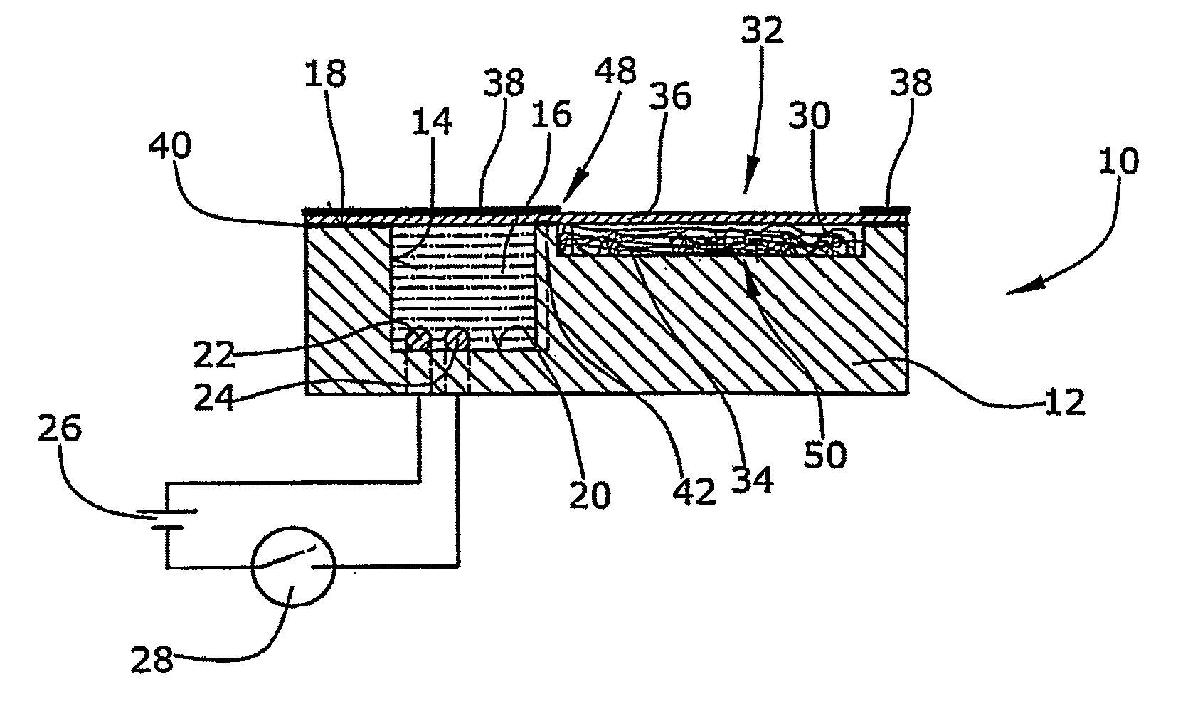
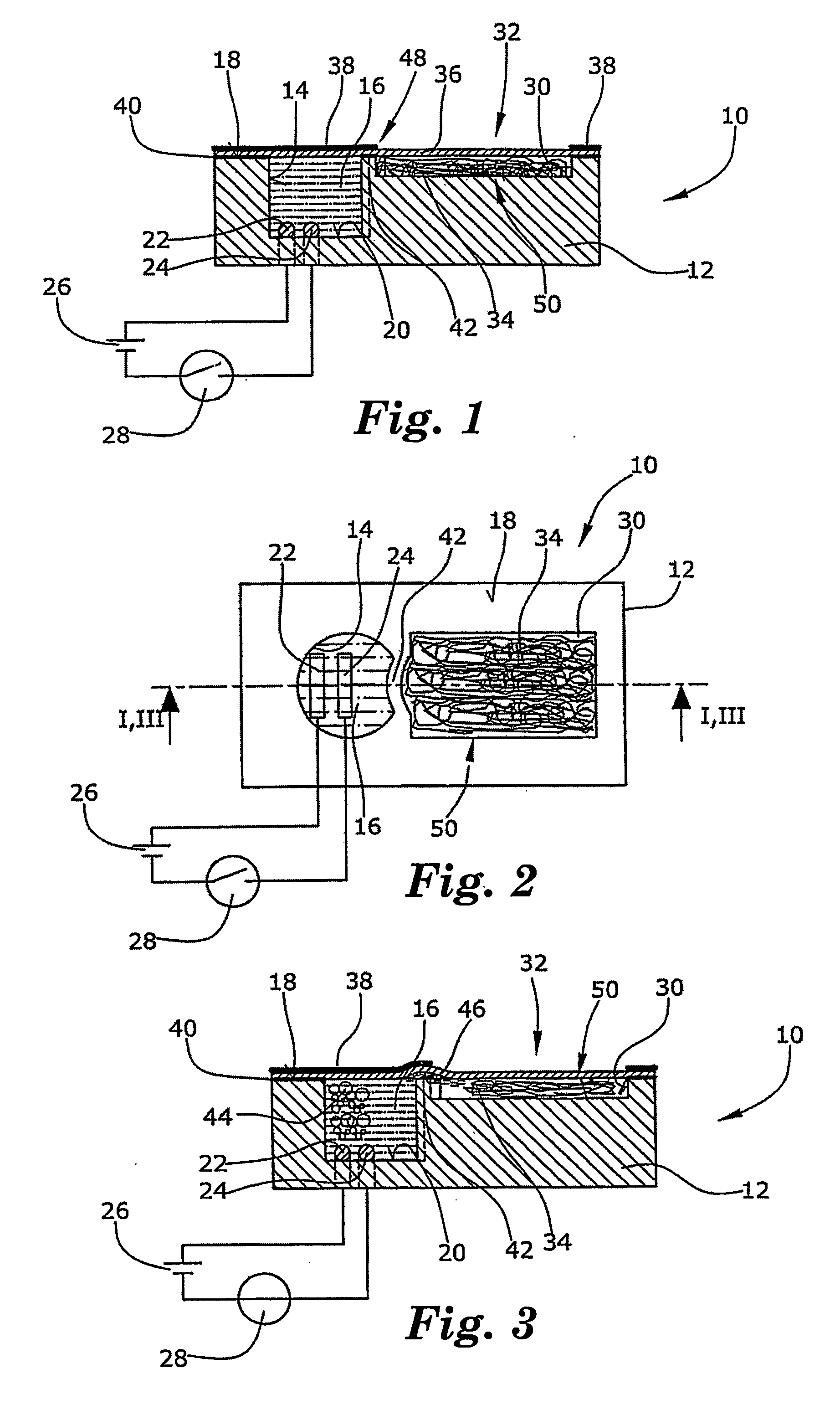
[0036] The working principal of the invention will be explained hereinbelow referring to FIGS. 1 to 3 showing a non-reversible bistable display device 10. The display device 10 comprises a substrate 12 made of a non conductive material such as molded synthetic material, a foil, or glass. Most preferably the substrate 12 comprises an electrically insulating material. Within the substrate 12 there is provided a chamber 14 containing an electrolyte 16. As can be seen from FIGS. 1 and 3 the chamber 14 is open to the top side 18 of the substrate 12. Within the chamber 14 and preferably at the bottom 20 thereof, there are arranged two electrodes 22,24 connected to a voltage source 26 via a switch 28.

[0037] Beside the chamber 14 within the top side 18 of the substrate 12 there is arranged another recess 30 filled with a porous element 32 provided as a non-woven fabric 34. This non-woven fabric comprises synthetic fibers, for example fibres of polypropylene or polyethylene. However, other f...

embodiment 60

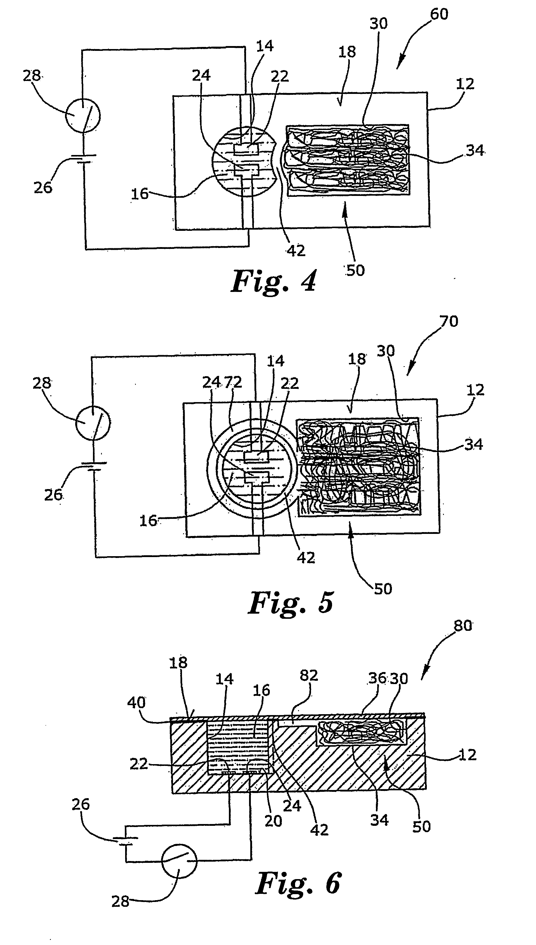
[0045] In particular, FIG. 4 is provided with a substrate 12 manufactured in molded interconnect device (MID) technique. This technique is known to those skilled in the art for forming three dimensional printed circuit boards. The electrodes 22,24 can be formed as electrically conductive traces along the top surface 18 of the substrate 12 and down into the chamber 14. As in FIGS. 1 to 3, the edge 42 between the chamber 14 and the receiving space 50 (recess 30) at the top side 18 of the substrate 12 is curved towards the chamber 14 resulting in a concentration of the forces for releasing the film 36 from the edge 42.

[0046] In FIG. 5 an embodiment of a display device 70 is shown in which an annular channel 72 is arranged around the chamber 14 wherein the annular channel 72 is in fluid communication with the receiving space 50. The edge 42 between the chamber 14 and the receiving space 50 is annular. Due to the surrounding channel 72 irrespective of where the film 36 will release from ...


PUM

PropertyMeasurementUnit
electrical voltageaaaaaaaaaa
currentaaaaaaaaaa
volumeaaaaaaaaaa

Abstract

The display device (10) capable of irreversibly switching from a first indicating state to a second indicating state comprises a chamber (14) containing an electrolytic liquid (16) and having at least one exit opening (46), and at least two electrodes (22,24) located in said chamber (14) and in contact with said electrolytic liquid (16) as well as subjectable to electric voltage, wherein, upon application of electric voltage of a predetermined level to said electrodes (22,24), gas is generated in said chamber (14) causing the pressure within said chamber (14) to exceed a threshold value such that liquid (16) irreversibly exits said chamber (14) through said at least one exit opening (46) thereby switching from the first indicating state to the second indicating state.

Description

BACKGROUND OF THE INVENTION [0001] 1. Field of the Invention [0002] The present invention relates to a non-reversible display device capable of irreversibly switching from a first indicating state to a second indicating state. [0003] 1. Related Prior Art [0004] Several indicating or displaying devices of different types and technologies are known in the prior art. Among these types of indicating or displaying devices there are electrochrome display devices (see e.g. DE-A-25 45 391 and DE-A-198 25 371), electroluminescent display devices (see e.g. DE-A-100 42 500), and the widely spread LCD display devices. Moreover, indicating devices are known in which the change of an indicating state results from a chemically induced change of colour (see e.g. EP-B-0 081 031 and DE-A-44 43 470). [0005] The problem with all of the above-identified types of display devices is that maintaining one of the two indicating states requires the provision of energy of a power supply. As soon as power is no...

Claims


Application Information

Patent Timeline
Patent Type & Authority Applications(United States)
IPC IPC(8): G02F1/1335G02B26/02
CPCG02B26/004
Inventor SCHUMACHER, KNUTKUEPPER, ANTONSCHULZE, GERHARD FRIEDRICH WAITER
Owner 3M INNOVATIVE PROPERTIES CO
Why Eureka
Try Eureka