
Wireless line control system, centralized control apparatus, wireless line control method used therein and program therefor

a wireless line and control system technology, applied in the direction of network topologies, wireless commuication services, connection management, etc., can solve the problems of many connected user terminals, instantaneous interruption or disconnection, and long period of disconnection at connected user terminals, and achieve high load

Inactive Publication Date: 2007-05-03
NEC CORP
View PDF6 Cites 27 Cited by
  • Summary
  • Abstract
  • Description
  • Claims
  • Application Information

AI Technical Summary

Benefits of technology

[0010] In consideration of the above, an object of the present invention is to solve the above problems by providing a wireless line control system, centralized control apparatus, wireless line control method used therein and program therefor which are capable of reducing control signals to wireless nodes with high loads as well as reducing occurrences of instantaneous interruption or disconnection at user terminals connected to the wireless nodes.
[0036] By arranging the present invention to have the following configuration and to perform the following operations, the effects of reduction of control signals to wireless nodes with high loads as well as reduction of occurrences of instantaneous interruption or disconnection at user terminals connected to the wireless nodes may be achieved.

Problems solved by technology

Additionally, in the conventional wireless mesh network, since switching of relay radio is performed within the network in a high-load state during which many user terminals are connected, instantaneous interruption or disconnection occurs at many of the connected user terminals.
Furthermore, in the conventional wireless mesh network, since switching of destinations is performed by searching wireless nodes to be alternative destinations after radio wave conditions of relay radio between wireless nodes have deteriorated, instantaneous interruption or a long period of disconnection occur at the connected user terminals in cases where no destinations could be found or where traffic at destinations are high.

Method used


Image

  • Wireless line control system, centralized control apparatus, wireless line control method used therein and program therefor
  • Wireless line control system, centralized control apparatus, wireless line control method used therein and program therefor
  • Wireless line control system, centralized control apparatus, wireless line control method used therein and program therefor

Examples


Embodiment Construction

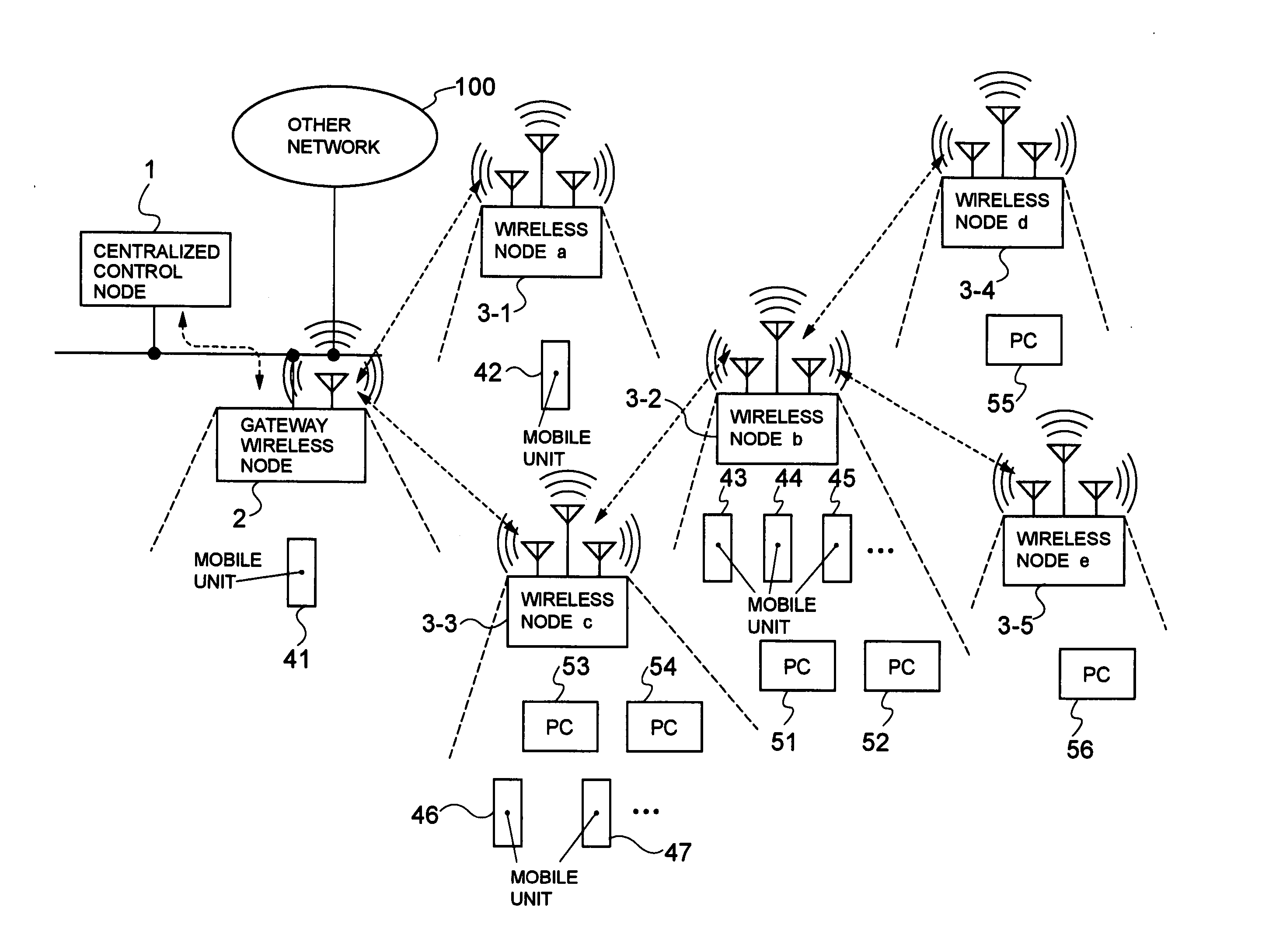
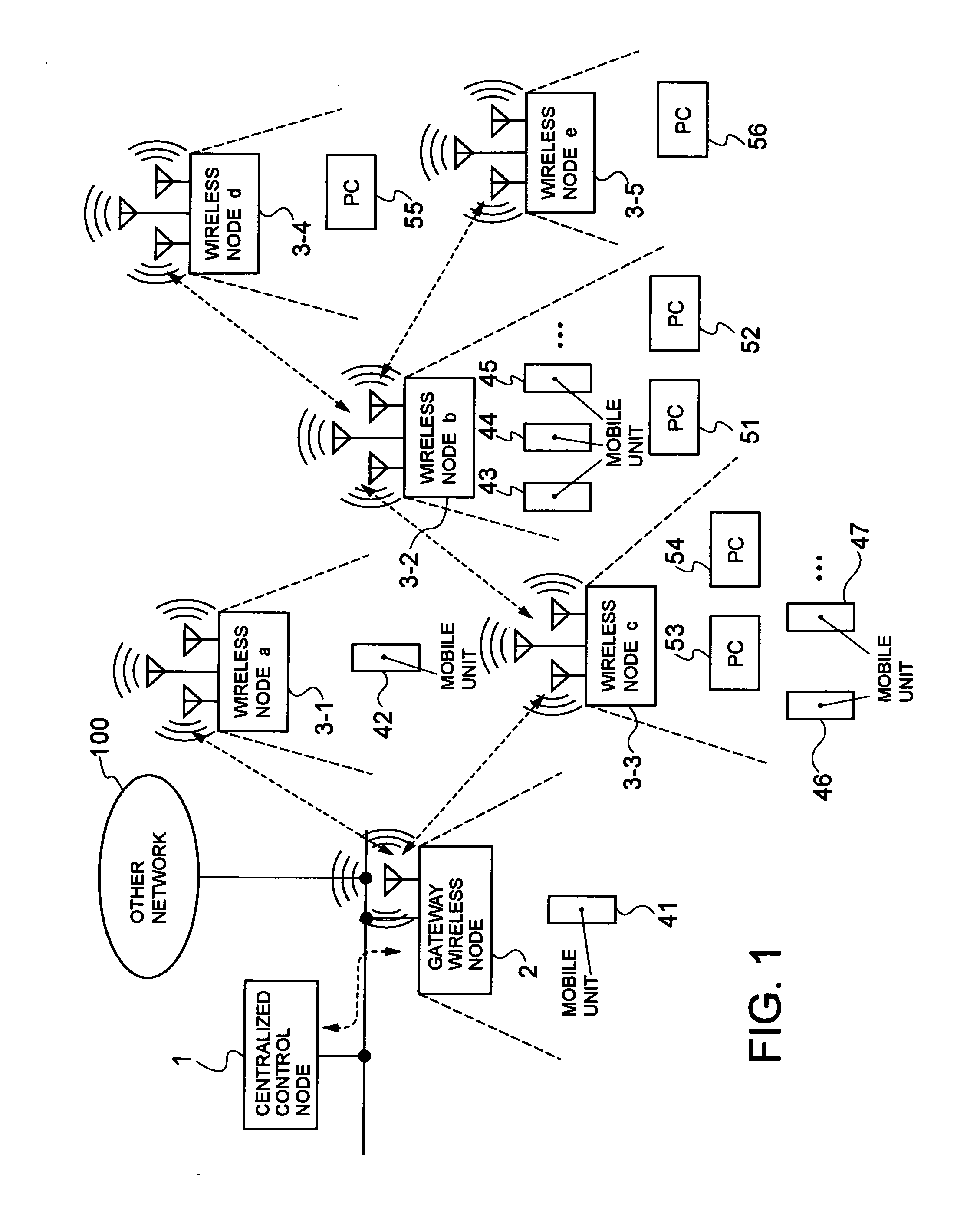
[0046] Embodiments of the present invention will now be described with reference to the drawings. FIG. 1 is a block diagram showing a configuration of a wireless line control system according to an embodiment of the present invention. In FIG. 1, the wireless line control system according to an embodiment of the present invention is comprised of a centralized control node 1, a gateway wireless node 2, wireless nodes (a to e) 3-1 to 3-5, and user terminals A such as mobile units 41 to 47 and PCs (personal computers) 51 to 56.

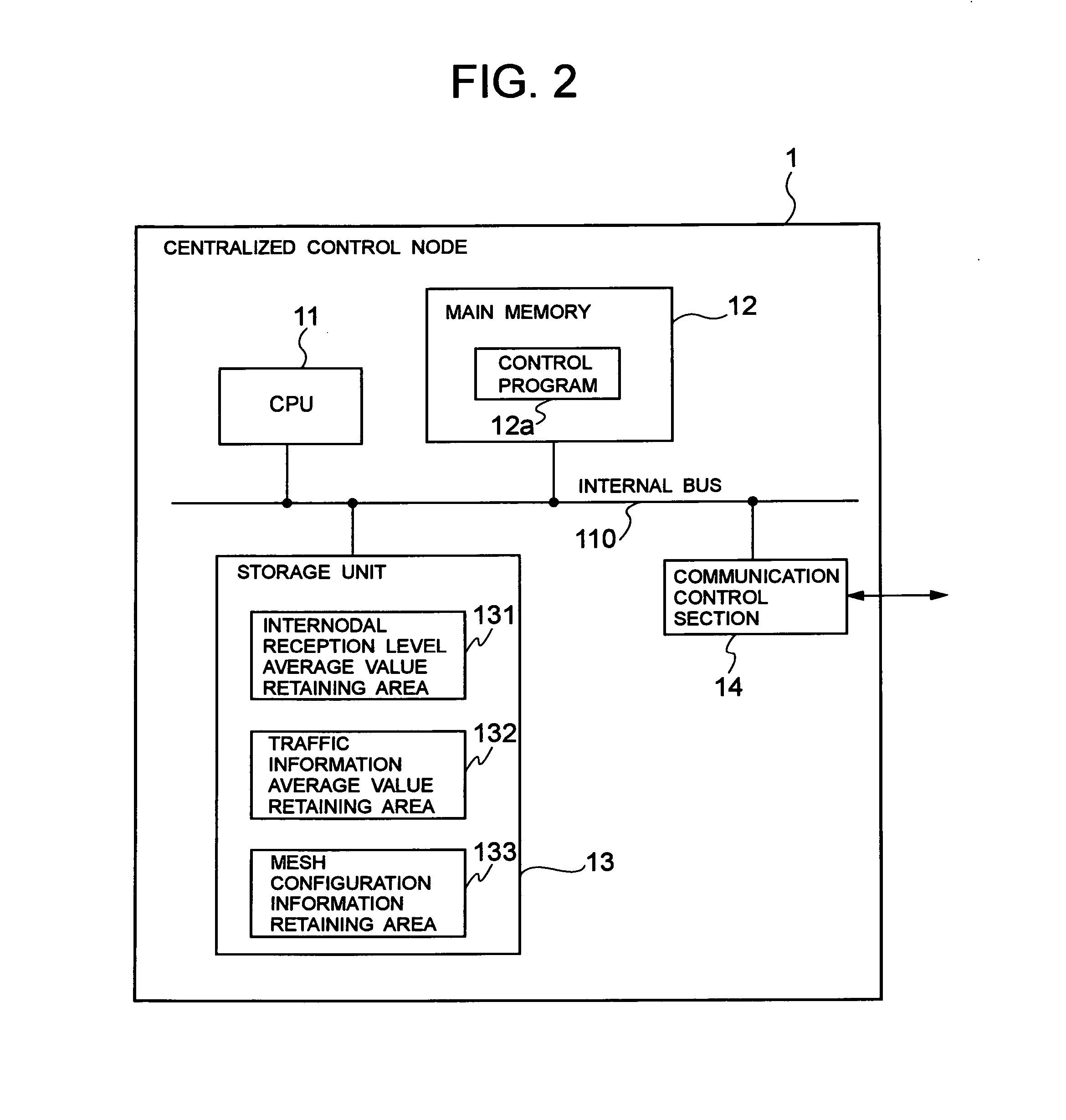
[0047] The centralized control node 1 is equipped with a function for collecting reception levels which indicate radio wave propagation states between the wireless nodes and information indicating traffic states at the wireless nodes from each wireless node (a to e) 3-1 to 3-5, a function for analyzing and storing the collected information, a function for determining a configuration of a wireless mesh network that is appropriate for future load patterns based on ...


PUM


Abstract

A wireless line control system capable of reducing control signals to wireless nodes with high loads as well as reducing instantaneous interruption or disconnection at user terminals connected to the wireless nodes is provided. In a1 to a3, centralized control node requests reception levels which indicate radio wave propagation states between wireless nodes from each wireless node and acquires the reception levels, and calculates and stores average values thereof. In a4 to a6, the centralized control node requests traffic information from each wireless node and acquires the traffic information, and calculates and stores average values thereof. Based on the averaged historical traffic information and reception levels between wireless nodes, in a7 and a8, the centralized control node determines a configuration of a wireless mesh network which is appropriate from the present to the future, and transmits configuration instructions to each wireless node according to the determined wireless mesh network configuration.

Description

BACKGROUND OF THE INVENTION [0001] 1. Field of the Invention [0002] The present invention relates to a wireless line control system, a centralized control apparatus, a wireless line control method used therein and a program therefor. In particular, the present invention relates to controlling wireless lines in a wireless mesh network. [0003] 2. Description of the Prior Art [0004] Conventionally, as a wireless mesh network, a network has been proposed which distributively arranges wireless terminals at certain intervals in a mesh pattern to configure a wireless mesh, and transfers packet data between mutually adjacent wireless terminals to relay the packet data to a destination terminal (for instance, refer to Japanese Patent Laid-Open No. 2000-115171). [0005] In this wireless mesh network, congestion processing is performed by wireless terminals by changing transmission speed according to the volume of data in the network or changing transfer rates according to destination of transm...

Claims


Application Information

Patent Timeline
IPC IPC(8): H04Q7/00H04B7/26H04W24/00H04W28/18H04W40/18H04W40/22H04W40/24H04W76/04H04W84/00H04W84/12H04W84/18H04W88/16
CPCH04W40/18H04W40/22H04W40/246H04W76/04H04W84/00H04W84/18H04W88/16H04W76/20
Inventor KATO, HIDENORI
Owner NEC CORP
Learn More