Integrated bladed fluid seal

Active Publication Date: 2007-05-03
RAYTHEON TECH CORP
View PDF5 Cites 38 Cited by
  • Summary
  • Abstract
  • Description
  • Claims
  • Application Information

AI Technical Summary

Benefits of technology

[0010] In accordance with the present invention, there are provided rotor to stator interface seals f

Problems solved by technology

The interfaces of the rotating blade stages and stationary vane stages are particularly difficult to seal due to the differences in thermal and centrifugal growth between the rotors and the cases.
The high relative speeds, extremely high temperatures and pressures also present seal design challenges in the turbines.
The supports are independent components, adding to the manufacturing costs and co

Method used


Image

  • Integrated bladed fluid seal
  • Integrated bladed fluid seal
  • Integrated bladed fluid seal

Examples


Embodiment Construction

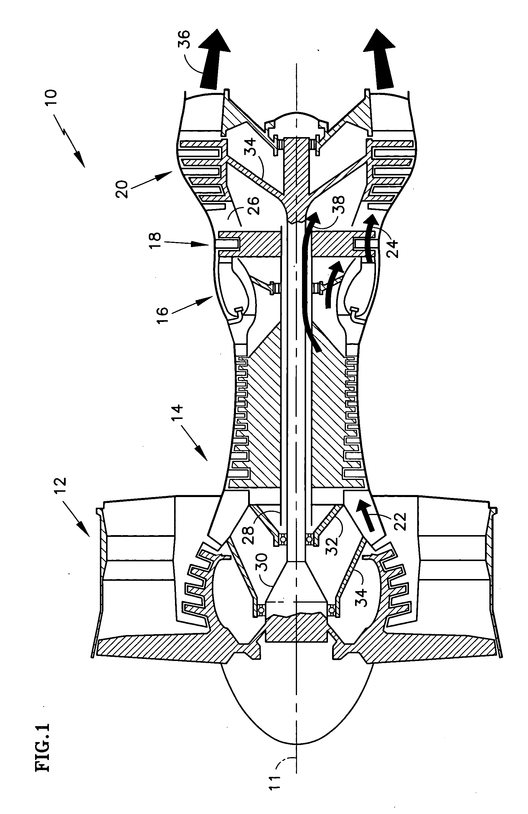
[0027] The major sections of a typical gas turbine engine 10 of FIG. 1 include in series, from front to rear and disposed about a central longitudinal axis 11, a low-pressure compressor 12, a high-pressure compressor 14, a combustor 16, a high-pressure turbine 18 and a low-pressure turbine 20. A working fluid 22 is directed rearward through the compressors 12, 14 and into the combustor 16, where fuel is injected and the mixture is burned. Hot combustion gases 24 exit the combustor 16 and expand within an annular duct 26, driving the turbines 18, 20. The turbines 18, 20, in turn drive coupled compressors 14, 12 via concentric shafts 28, 30, forming a high rotor spool 32 and a low rotor spool 34 respectively. Although a dual spool engine 10 is depicted in the figure, three spool engines 10 are not uncommon. The combustion gases exit the engine 10 as a propulsive thrust 36, used to power an aircraft or a free turbine. A portion of the working fluid 22 is bled from the compressors 12, 1...


PUM


Abstract

Disclosed are various embodiments of a gas turbine blade to vane interface seal for restricting leakage of cooling air and improving the apportioning of the cooling air to the seal. Accordingly, a turbine rotor contains a first and a second stage of radially extending and circumferentially distributed blades. The stages are separated axially from one another by an annular coupling located radially inboard of the blades, forming a chamber therebetween. Interposed between the blade stages is a vane stage. The vane stage contains a land, facing radially inwardly. A ring projects axially from each of the first and second blade stages towards the vane stage. A ring may also project radially from the coupling towards the vane stage. The rings radially cooperate with the land and together form the blade to vane interface seal. The coupling contains an aperture for radially introducing a cooled fluid to the chamber for use in cooling the seal.

Description

CROSS-REFERENCE TO RELATED APPLICATIONS [0001] This application discloses subject matter related to copending U.S. patent applications “HAMMERHEAD FLUID SEAL” (Ser. No. 11 / 146,801), “COMBINED BLADE ATTACHMENT AND DISK LUG FLUID SEAL” (Ser. No. 11 / 146,798) and “BLADE NECK FLUID SEAL” (Ser. No. 11 / 146,660), each filed on Jul. 7, 2005.BACKGROUND OF THE INVENTION [0002] (1) Field of the Invention [0003] The invention relates to gas turbine engines, and more specifically to a cooled fluid sealing arrangement disposed between blades and vanes of such engines. [0004] (2) Description of the Related Art [0005] Gas turbine engines operate by compressing ambient air with a forward compressor, injecting a fuel, burning the air-fuel mixture in a central combustor and converting the energy of combustion into a propulsive force. Combustion gases exit the combustor through an annular duct, where the gases drive one or more axial stages of circumferentially distributed turbine blades. Each bladed st...

Claims


Application Information

Patent Timeline
IPC IPC(8): F04D29/08
CPCF01D5/081F01D11/001F01D11/02F02C7/28Y02T50/671Y02T50/673Y02T50/676Y02T50/60
Inventor ALVANOS, IOANNISAGRAWAL, RAJENDRAREINHARDT, GREGORY E.
Owner RAYTHEON TECH CORP
Why Eureka
Try Eureka