Heater unit manufacturing method

a manufacturing method and heating unit technology, applied in the direction of lighting and heating apparatus, pedestrian/occupant safety arrangement, vehicular safety arrangement, etc., can solve the problems of dusty surrounding area of heating object, temperature drop in fluid as it passes through the valve, etc., to achieve energy efficient uniform heating, reduce the number of parts, and reduce the cost

Inactive Publication Date: 2007-05-03
TOKYO TECHNOLOGICAL LABO
View PDF5 Cites 6 Cited by
  • Summary
  • Abstract
  • Description
  • Claims
  • Application Information

AI Technical Summary

Benefits of technology

[0025] That is, according to the heater unit manufacturing method, the heater unit may be formed according to the contour of a heating object. In addition, the external surface of the heater unit is solidified by the impregnation of heat resistant resin and heat treatment, and a heat insulating layer constituted by multitudes of fibers and airspace is formed inside of the heater unit. Consequently, while providing heat insulating properties, the heater unit is free from dust emissions, including fiber dispersal from the surface of the heater unit. Thus, it has no adverse effects on environment and human body. Accordingly, any plastic or metal cover for the heater unit is not required for preventing dust emissions. Further, the heater unit may be formed integrally according to the contour of a heating object, and a heating element is mounted therein. This allows the heater unit to be manufactured at low cost with less number of parts. Still further, the heating element may be disposed adjacent to a heating object of any configuration, which allows energy efficient uniform heating. That is, it is comparatively free to set the region of heating object, and the heater unit may be readily formed such that the heating element is placed in close contact with the heating object, which may enhance the accuracy of the temperature to be maintained.
[0026] Further, in the case where organic silicon carbide series paint is used as the heat resistant resin to be impregnated in the heat insulating housing block, a high heat resistant heater unit may be manufactured, which is capable of high temperature heating of approximately 350 degrees Celsius.
[0027] Still further, in the case where the heat treating step compri

Problems solved by technology

Still further, for a piping system that carries high temperature gas or liquid, a temperature drop in the fluid as it passes through the valve is a problem when the fluid needs to be carried through the piping system without any appreciable temperature drop.
These heaters have, therefore, caused various problems.
For example, the mantle heater type heating mechanism described above has a problem that it often emits dust and the surrounding area of the heating object becomes dusty.
This has, however, resulted in another problem that the structure is complicated, and the heater is costly due to a larger number of parts.
Further, it is difficult to cover a heating object in close contact if a heating object has a complicated configuration.
This has caused energy loss due to inefficient heat transfer from the heater to the heating object.
This may result in larger number of parts and require greater manpower for assembly.
In the heater disclosed in Japanese Unexamined Patent Publication No. 2001-349468, the heater unit is provided at a plurality of sections a

Method used


Image

  • Heater unit manufacturing method
  • Heater unit manufacturing method
  • Heater unit manufacturing method

Examples


Embodiment Construction

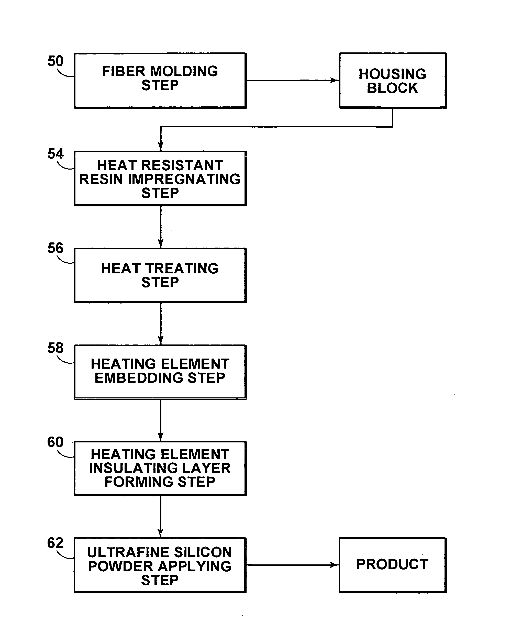
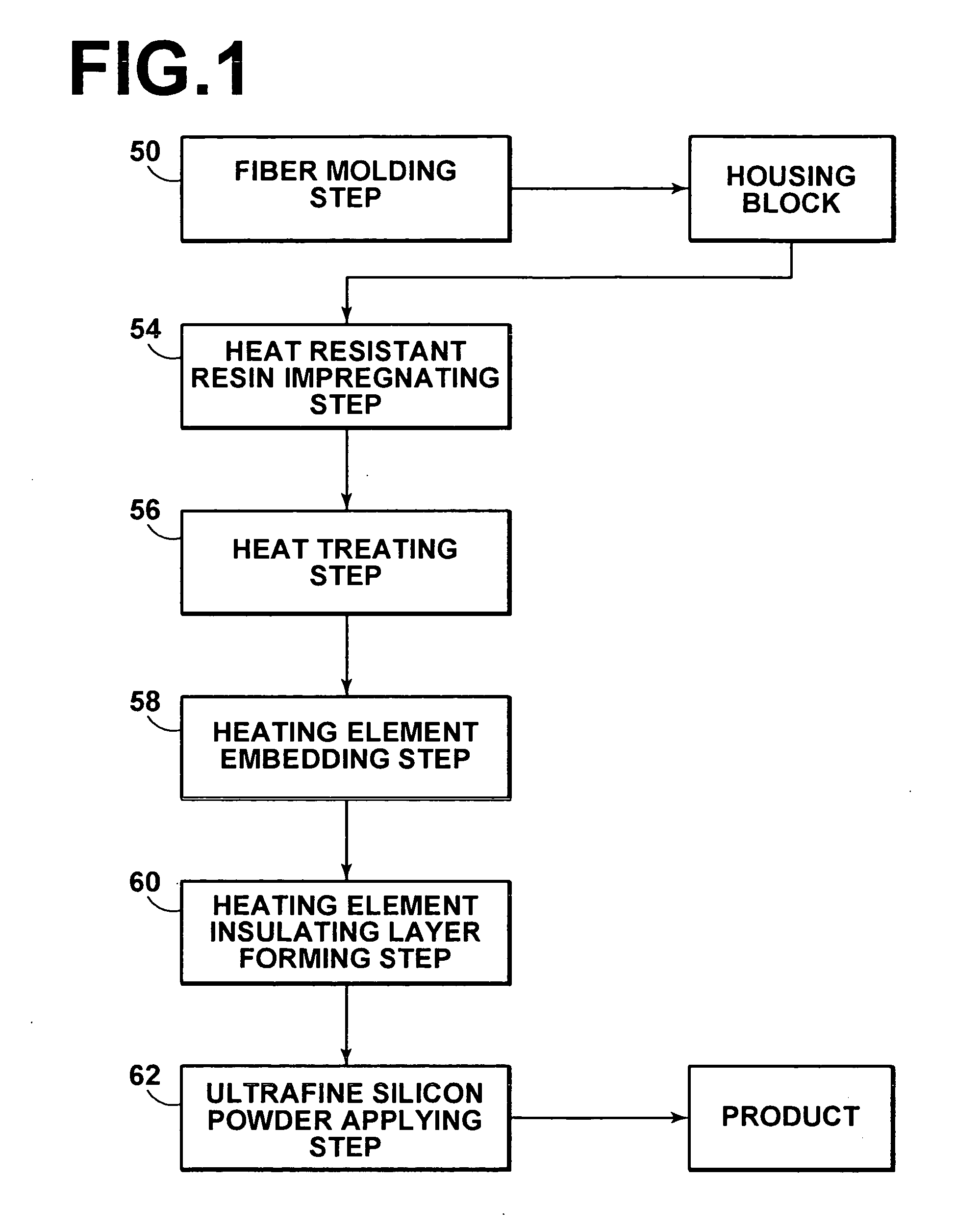
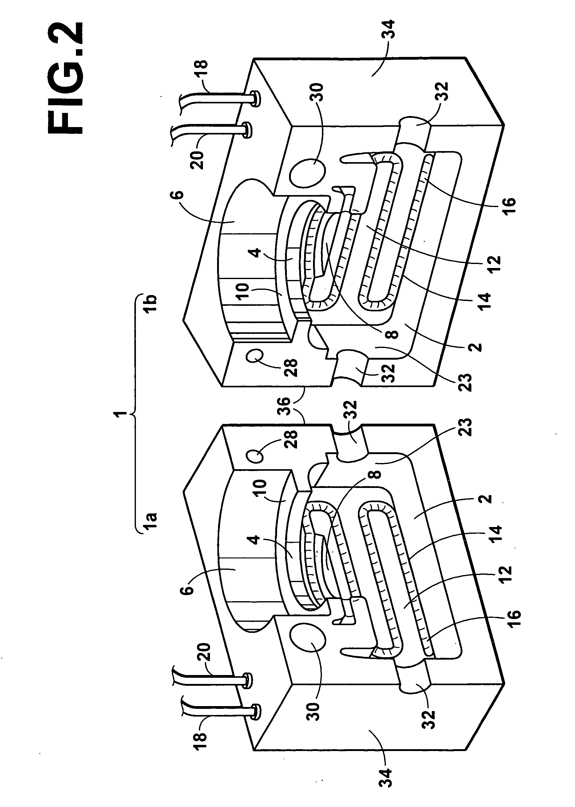
[0036] Hereinafter preferred embodiments of the heater unit manufacturing method (hereinafter, simply referred to as “manufacturing method”) according to the present invention will be described in detail with reference to the accompanying drawings. FIG. 1 is a flowchart illustrating the respective steps of the manufacturing method of the present invention. FIG. 2 is an exploded perspective view of an illustrative heater unit manufactured by the manufacturing method of the present invention. FIG. 3 is a perspective view of a valve which is an illustrative heating object of the heater unit shown in FIG. 2. FIG. 4 is a drawing illustrating the valve shown in FIG. 3 with the heater unit shown in FIG. 2 being mounted thereon.

[0037] First, an open / close valve 100 having comparatively complicated contour on which a heater unit 1 is to be mounted will be described with reference to FIG. 3. The entire valve is indicated by the reference numeral 100, which is connected to fluid pipes 102 thr...


PUM


Abstract

A heater unit manufacturing method constituted by the steps of: forming multitudes of inorganic fibers into a heat insulating housing block through molding; heat treating the heat insulating housing block after impregnating the block with heat resistant resin; and mounting a heating element inside of the heat treated heat insulating housing block.

Description

TECHNICAL FIELD [0001] The present invention relates to a heater unit manufacturing method. More specifically, the present invention is directed to a method for manufacturing a heater unit to be mounted on the heating object, such as piping and a valve. BACKGROUND ART [0002] For a valve mounted, for example, on a piping system that supplies gas to semiconductor manufacturing equipment or the like, it is necessary to prevent formation of dew condensation within the valve due to a temperature drop in the gas as it passes through the valve. In addition, a valve mounted on a piping system that carries liquid, which solidifies at a temperature near room temperature, it is necessary to prevent a blockage of the valve or development of accretion within the valve due to solidification of the liquid. Still further, for a piping system that carries high temperature gas or liquid, a temperature drop in the fluid as it passes through the valve is a problem when the fluid needs to be carried thr...

Claims


Application Information

Patent Timeline
IPC IPC(8): B60R21/16B32B7/02B32B9/00H05B3/40F16L53/00F24H1/00H01C17/00H05B3/20
CPCH01C17/00Y10T428/24992Y10T428/30Y10T428/1362
Inventor HASEGAWA, TEIJISUEMURA, SHUICHI
Owner TOKYO TECHNOLOGICAL LABO
Why Eureka
Try Eureka